
Exhaust gas recirculation management
- Make
- Fiat
- Model
- Bravo /Brava (182) Factory Service Manual
- Year
- 1995–2001
- Section
- Fuel system (1910 TD 100) › Exhaust gas recirculation management
EXHAUST GAS RECIRCULATION MANAGEMENT
The electronic control unit calculates the weight ratio between the "clean" intake air and the quantity of burnt gases which can be returned to the intake. Depending on the engine load, the temperature of the coolant, the atmospheric pressure and the quantity of intake air, the electronic control unit operates the Borg Warner solenoid valve which, in turn, activates the EGR valve, by means of a vacuum signal, thereby allowing the partial recirculation of the exhaust gases.
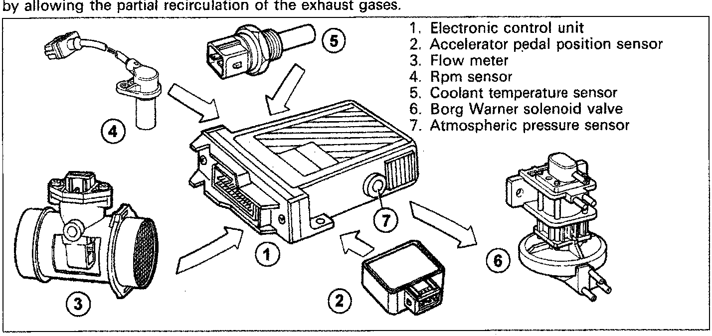
- Electronic control unit
- Accelerator pedal position sensor
- Flow meter
- Rpm sensor
- Coolant temperature sensor
- Borg Warner solenoid valve
- Atmospheric pressure sensor
AIR CONDITIONING SYSTEM MANAGEMENT
When the air conditioning is switched on, the compressor absorbs power from the engine which, when idling, tends to cut out. In order to prevent this problem, the control unit activates the fast idle function described previously.
Another function carried out by the control unit is that of interrupting the compressor supply if one of the following conditions occurs:
- Coolant temperature more than 110 °C;
- Exceeding of a certain rpm level (around 4500);
- High engine power request (strong acceleration).
In conditions 1 and 2 the supply is restored when the coolant temperature or engine rpm values go below the intervention level.
In condition 3 the interruption is only momentary and the supply is automatically restored after several seconds even in the high power request still exists.
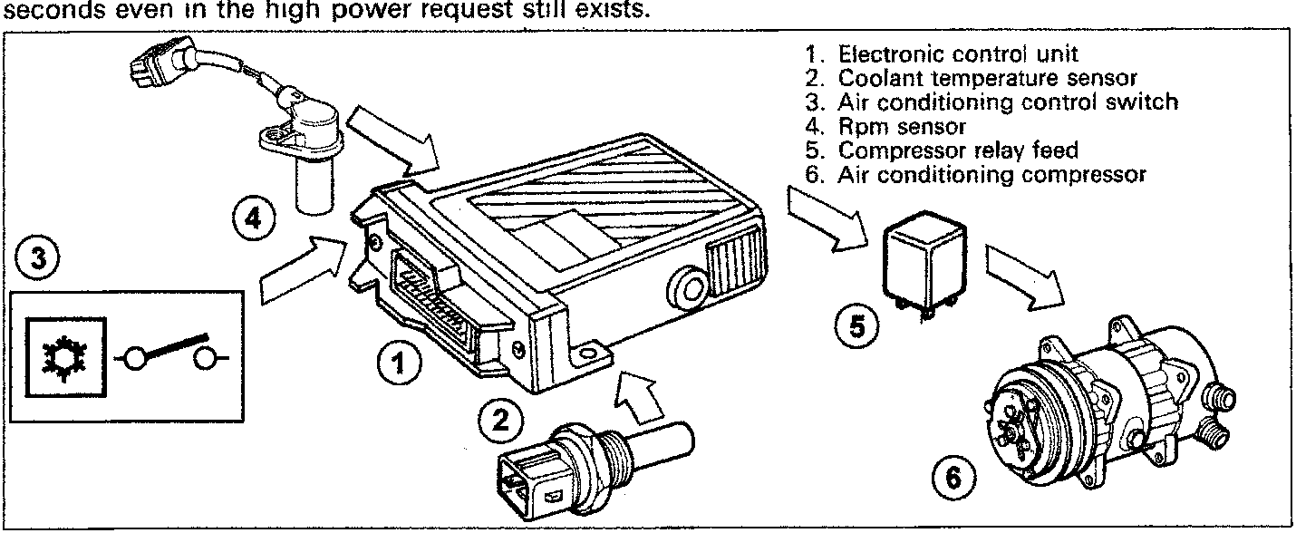
- Electronic control unit
- Coolant temperature sensor
- Air conditioning control switch
- Rpm sensor
- Compressor relay feed
- Air conditioning compressor
Parts & tools for this job For 1995 Fiat Bravo
- PARTExhaust gasketSearch: Fiat Bravo 1995 exhaust gasket
- TOOLPenetrating oilSearch: penetrating oil
- TOOLOBD2 scannerSearch: OBD2 scanner
Links open Amazon search results in a new tab. As an Amazon Associate I earn from qualifying purchases.