
Cam seal
- Make
- Fiat
- Model
- Bravo /Brava (182) Factory Service Manual
- Year
- 1995–2001
- Section
- Fuel system (1910 TD 100) › Cam seal
The functions of metering, pumping and distributing take place in the main section of the injection pump, known as the hydraulic head.
The hydraulic head is composed of two groups:
- - the hydraulic head stator;
- - the distributor rotor, made up of a single element and two pumping pistons.
The distributor rotor is coupled with the housing in the hydraulic head, whilst the pumping pistons are coupled with the housings in the rotor. This means that these parts are not interchangeable with others but constitute a single assembly.
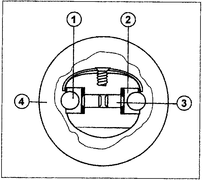
- Roller
- Roller carrier
- Small piston
- Cam seal
The fuel subject to the transfer pressure enters one of the ports in the hydraulic headl; the opening of this port is controlled by the movement of the metering valve connected to the mechanical regulator.
During the charging cycle, two ports in the rotor are aligned with two filling ports for the head stator. A metered quantity of fuel, regulated by the metering valve, enters the pumping element and moves the pumping pistons (3) away, pushing the group formed by the roller (1) and the roller carrier (2) outwards. By rotating the rotor interrupts the alignment between the charging and filling ports (end of charging cycle).
By continuing the rotation, one of the fuel supply ports coincides with one of the high pressure outlets.
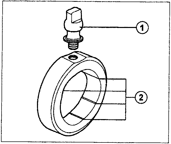
- Cam seal
- Cam seal bolt
Cam seal
The internal surface of the cam seal has lobes (1) which are diametrically opposite and is machined with precision.
The shape of the lobes causes the pressure movement in the pump, determines the duration of the injection stage and standardizes the supply cycles.
The cam seal bolt (2) connects the latter to the injection advance adjustment system. When the pump starts the injection cycle, the two roller and roller carrier units which are in contact with the pistons, start to move inwards under the force of the two opposing lobes.
This is the start of the injection.
Whilst the rotor continues to rotate, the rollers move upwards, until they reach the top of the lobes.
This marks the end of the injection.
Continuing the injeciton cycle, the rollers lose contact with the cam seal and the hydraulic head rotor returns to the low pressure condition ready for a new pressurizing cycle.
Parts & tools for this job For 1995 Fiat Bravo
- PARTFuel filterSearch: Fiat Bravo 1995 fuel filter
- TOOLFuel pressure test kitSearch: fuel pressure test kit
- TOOLFuel line disconnect toolSearch: fuel line disconnect tool
Links open Amazon search results in a new tab. As an Amazon Associate I earn from qualifying purchases.