
Adjusting injection advance (page 2 of 2)
- Make
- Fiat
- Model
- Bravo /Brava (182) Factory Service Manual
- Year
- 1995–2001
- Section
- Fuel system (1910 TD 100)
The transfer pump regulating valve is housed in the hydraulic head and carries out three distinct functions:
- creating the transfer pressure;
- controlling this pressure by maintaining a precise relationship between the transfer pressure and the rotation speed;
- pressurizing the fuel metering circuit each time it proves necessary.
The regulating valve consists of a valve casing (4) which contains a piston (2) and a spring (3). The force applied by the spring (3) can be adjusted by means of an external screw (5) and is opposed by another spring (1) which keeps the piston (2) in its original position.
Increasing the rotation speed of the transfer pump, increases the flow rate and consequently also increases the pressure acting on the piston (2).
When the piston (2) moves it compresses the regulating spring (3) and gradually places the ports (8) and (9) in contact allowing the fuel to return to the transfer pump inlet via the passage (7).
By increasing and decreasing the opening for the ports (8) and (9), the valve makes it possible to regulate the transfer pressure value.
The valve also has the function of filling the transfer pump to ensure priming during the starting stage. During this stage the lack of inlet pressure allows the spring (3) to extend and move the piston (2) which compresses the spring (1); the fuel in the connector (7) enters through the port (8) and, passing through the piston (2), comes out of the duct (10) reaching the transfer pump.
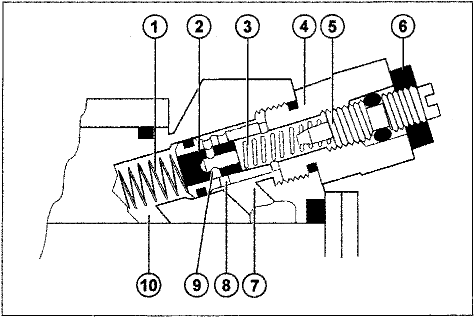
- Opposing spring
- Transfer pump regulating piston
- Regulating spring
- Regulating valve body
- Transfer pump adjustment screw
- Lock nut
- Regulated fuel return passage to the transfer pump
- Adjustment port
- Filling port
- Fuel inlet from the transfer pump
Parts & tools for this job For 1995 Fiat Bravo
- PARTFuel filterSearch: Fiat Bravo 1995 fuel filter
- TOOLFuel pressure test kitSearch: fuel pressure test kit
- TOOLFuel line disconnect toolSearch: fuel line disconnect tool
Links open Amazon search results in a new tab. As an Amazon Associate I earn from qualifying purchases.