
Electrical/electronic circuit
- Make
- Fiat
- Model
- Bravo /Brava (182) Factory Service Manual
- Year
- 1995–2001
- Section
- Fuel system (1910 TD 100) › Electrical/electronic circuit
ELECTRICAL/ELECTRONIC CIRCUIT
The electrical/electronic circuit for the fuel system basically comprises wiring, an electronic control unit and the following sensors and actuators:
- Rpm sensor
- Coolant temperature sensor
- Air flow meter
- Intake air temperature sensor
- Instrument injector
- Accelerator lever position sensor
- Fast idle solenoid valve
- Pre-heating control unit
Electronic control unit
The electronic control unit (ECU) is located below the glove compartment (right side) and is connected to the wiring by means of a 25 pin connector.
It receives all the information relating to the engine running conditions transmitted by the various sensors in addition to atmoshperic pressure information obtained by means of a sensor inside the actual control unit.
Through this data and with the aid of special programmes, the control unit is capable of carrying out the following operating strategies:
- injection advance management
- fast idle management
- exhaust gas recirculation management
- air conditioning system management
- heater plugs pre/post heating management
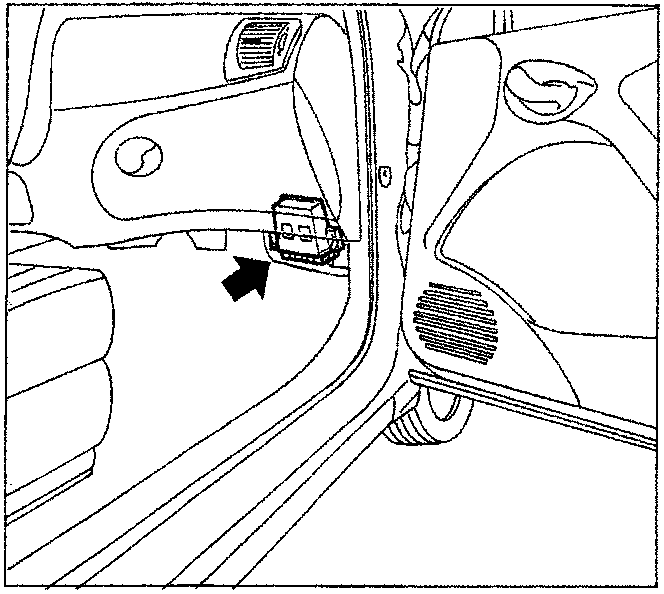
Location of electronic unit
Parts & tools for this job For 1995 Fiat Bravo
- TOOLDigital multimeterSearch: automotive digital multimeter
- PARTAssorted fuse kitSearch: car fuse assortment kit
- TOOLWire crimper and connector kitSearch: wire crimper connector kit
Links open Amazon search results in a new tab. As an Amazon Associate I earn from qualifying purchases.