
High pressure supply valves (page 3 of 3)
- Make
- Fiat
- Model
- Bravo /Brava (182) Factory Service Manual
- Year
- 1995–2001
- Section
- Fuel system (1910 TD 100)
The speed regulator connects the accelerator lever (1) to the metering valve (7). Its function is to control the idle speed (and the fast idle) and the maximum engine speed.
The minimum/maximum regulator unit (mini/maxi device) (2) consists of a pre-loaded spring housed in a steel tube which connects the accelerator lever (1) to the upper part of the regulator plate (3). The regulator plate, in turn, causes the metering valve (7) to rotate by means of a connecting rod (5).
A spring (14), fixed to the front section of the regulator plate, controls the idle speed.
The mass carrier (10), which is fixed to the control shaft (11), contains a certain number of masses (9) subject to a centrifugal force which varies according to the engine rotation speed.
In idling conditions the centrifugal force acting on the masses is weak and the regulator plate is balanced between the force exerted by the masses (9) and the force of the spring (14) resting on the idle shaft.
During acceleration, the accelerator lever (1) moves the metering valve (7), via the regulator rod (5), towards the completely open position.
The centrifugal force exerted by the masses increases, but remains lower than the pre-loading of the mini/maxi device (2) spring.
This means that the connection between the metering valve (7) and the accelerator lever (1) is direct.
During the adjustment stage, or when the speed reached increases the centrifugal force of the masses to such an extent as to overcome the mini/maxi device spring pre-loading force, the regulator controls the position of the metering valve (7).
In this case the connection between the metering valve (7) and the accelerator lever (1) is no longer direct.
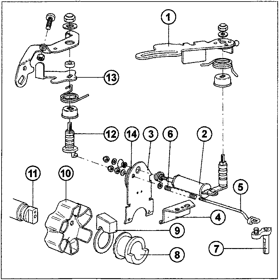
- Accelerator lever
- Mini/maxi device
- Regulator plate
- Regulator bracket
- Regulator rod
- Regulator rod spring
- Metering valve
- Regulator sleeve
- Regulator masses
- Mass carrier
- Drive shaft
- Idle shaft
- Idle lever
- Idle spring
Parts & tools for this job For 1995 Fiat Bravo
- PARTEngine gasket setSearch: Fiat Bravo 1995 engine gasket set
- TOOLTorque wrenchSearch: 3/8 inch torque wrench
- TOOLFeeler gauge setSearch: feeler gauge set
Links open Amazon search results in a new tab. As an Amazon Associate I earn from qualifying purchases.