
Adjusting injection advance
- Make
- Fiat
- Model
- Bravo /Brava (182) Factory Service Manual
- Year
- 1995–2001
- Section
- Fuel system (1910 TD 100) › Adjusting injection advance
Adjusting injection advance
The injection advance adjustment system makes it possile to vary the start of the injection so that it takes place at the optimum time in all engine operating conditions.
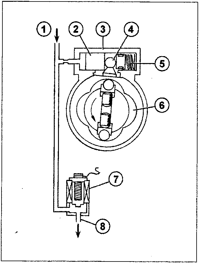
The system comprises a small piston (2) which slides in the cylinder (3) and is opposed by the spring (5).
This piston is connected to the cam seal (6) by means of a threaded pin with a spherical head (4).
If the solenoid valve (7) is not activated, the transfer pressure (1), acting on the piston (2), moves the actual piston overcoming the resistance of the spring (5) and causes the rotation of the cam seal (6), through the pin (4), in relation to the pump control shaft, towards the maximum advance position.
The activation of the solenoid valve (7) allows the fuel to flow towards the vehicle tank via the return pipe (8). This causes a decrease in the pressure acting on the piston (2) allowing the spring (5) to extend fully and, rotate the cam seal towards the mimimum advance position by means of the pin (4).
In this way by varying the solenoid valve (7) opening/closing frequency, the electronic control unit modulates the value of the pressure acting on the piston (2) thereby continuously regulating the start of the injection.
Transfer pump
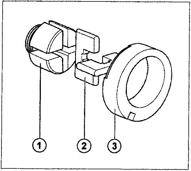
The transfer pump, which is the volumetric type (inlet and pressure), consists of a rotor (1), an eliptical seal (3) and two rigid brushes (2).
During rotation, the brushes (2) slide in the rotor (1) following the profile of the eliptical seal (3) which is offset in relation to the rotor. As the volume in the chamber increases, a vacuum is created upstream of the blade with the consequent intake of fuel from the tank; the volume decreases downstream of the vane and consequently the fuel in the circuit is supplied under pressure.
Parts & tools for this job For 1995 Fiat Bravo
- PARTFuel filterSearch: Fiat Bravo 1995 fuel filter
- TOOLFuel pressure test kitSearch: fuel pressure test kit
- TOOLFuel line disconnect toolSearch: fuel line disconnect tool
Links open Amazon search results in a new tab. As an Amazon Associate I earn from qualifying purchases.