
Connector wiring
- Make
- Fiat
- Model
- Bravo /Brava (182) Factory Service Manual
- Year
- 1995–2001
- Section
- Fuel system (98 range, 1242 16v) › Connector wiring
10 EngineConnector wiring
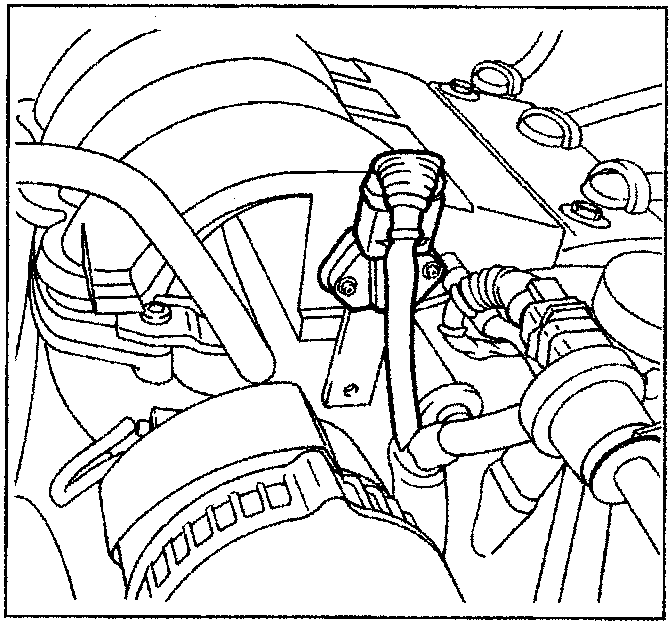
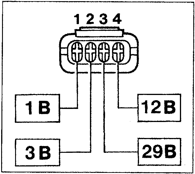
The intake air pressure and temperature sensor is an integrated component that measures pressure and temperature inside the inlet manifold. The injection control unit uses both items of information to define the amount of air taken in by the engine. This information is then used to compute injection time and ignition point. The sensor is fitted on the intake manifold.
| Temperature (°C) | Resistance (M) |
|---|---|
| -40 | 52600-38700 |
| -20 | 17500-13500 |
| 0 | 6500-5300 |
| 10 | 4200-3400 |
| 20 | 2700-2300 |
| 30 | 1850-1550 |
| 40 | 1300-1050 |
| 50 | 920-750 |
| 60 | 650-530 |
| 80 | 360-290 |
| 100 | 210-160 |
Connector wiring
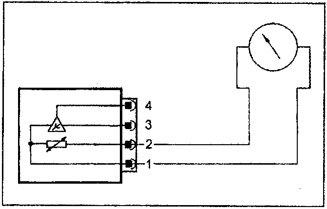
Checking the resistance
The table shows resistance values that the temperature sensor (NTC thermistor) may assume as temperature changes. These values may be measured by connecting an ohmmeter as shown in the diagram.
Parts & tools for this job For 1995 Fiat Bravo
- TOOLDigital multimeterSearch: automotive digital multimeter
- PARTAssorted fuse kitSearch: car fuse assortment kit
- TOOLWire crimper and connector kitSearch: wire crimper connector kit
Links open Amazon search results in a new tab. As an Amazon Associate I earn from qualifying purchases.