
Fuel manifold
- Make
- Fiat
- Model
- Bravo /Brava (182) Factory Service Manual
- Year
- 1995–2001
- Section
- Fuel system (98 range, 1242 16v) › Fuel manifold
FUEL MANIFOLD
The fuel manifold, which has the task of distributing the fuel to the injectors, is made from die-cast aluminium and incorporates the housings for the injectors and the air bleed valve.
The fuel inlet has a rapid attachment. Since the system is the returnless type, there is no recirculation pipe.
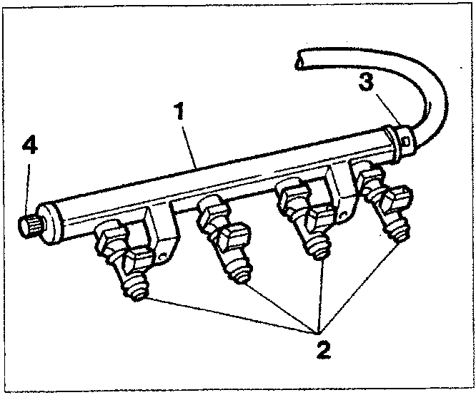
- Fuel manifold
- Injectors
- Fuel supply connector
- Bleed valve
INJECTORS
The injectors have the task of supplying the amount of fuel required for the operation of the engine: the fuel is injected into the inlet duct, immediately upstream of the inlet valve.
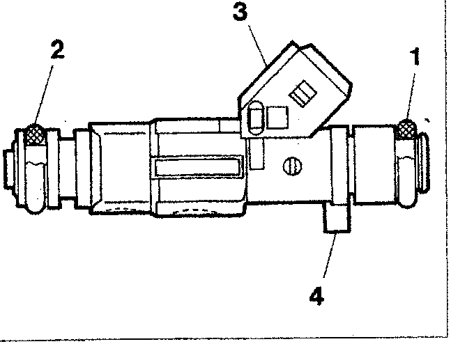
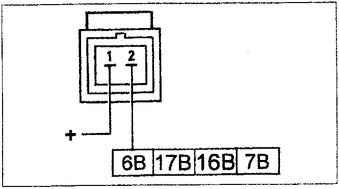
The injectors are the top-feed type and there is an electrical winding connected to the connector (3) terminals.
When the current passes through the winding, the magnetic field which is created attracts the shutter causing the opening of the injector and the flow of fuel.
There are two seals on the fuel manifold side (1) and the inlet manifold side (2). A reference (4) determines the angular position of the injector and the correct position of the jets in relation to the inlet valves.
Wiring connector
The injector resistance can be measured by disconnecting the connector and connecting an ohmmeter as shown in the diagram.
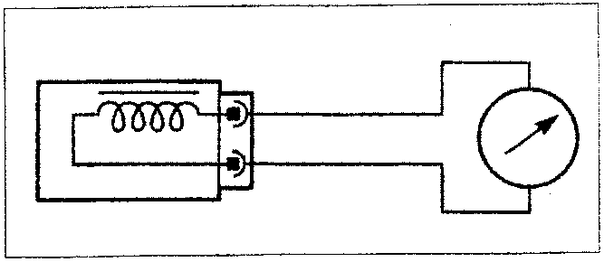
Resistance value: 14.5±5% ohm.
Parts & tools for this job For 1995 Fiat Bravo
- PARTFuel filterSearch: Fiat Bravo 1995 fuel filter
- TOOLFuel pressure test kitSearch: fuel pressure test kit
- TOOLFuel line disconnect toolSearch: fuel line disconnect tool
Links open Amazon search results in a new tab. As an Amazon Associate I earn from qualifying purchases.