
Sensors (page 2 of 2)
- Make
- Fiat
- Model
- Bravo /Brava (182) Factory Service Manual
- Year
- 1995–2001
- Section
- Fuel system (98 range, 1910 JTD)
10 EngineSensors · page 2 of 2
The fuel supply circuit is operationally divided into a low pressure circuit and a high pressure circuit. The low pressure circuit consists of a tank, multi-purpose valve, auxiliary electric pump immersed in the tank and return manifold.
The high pressure circuit consists of a radialjet pressure pump, supply manifold and injectors.
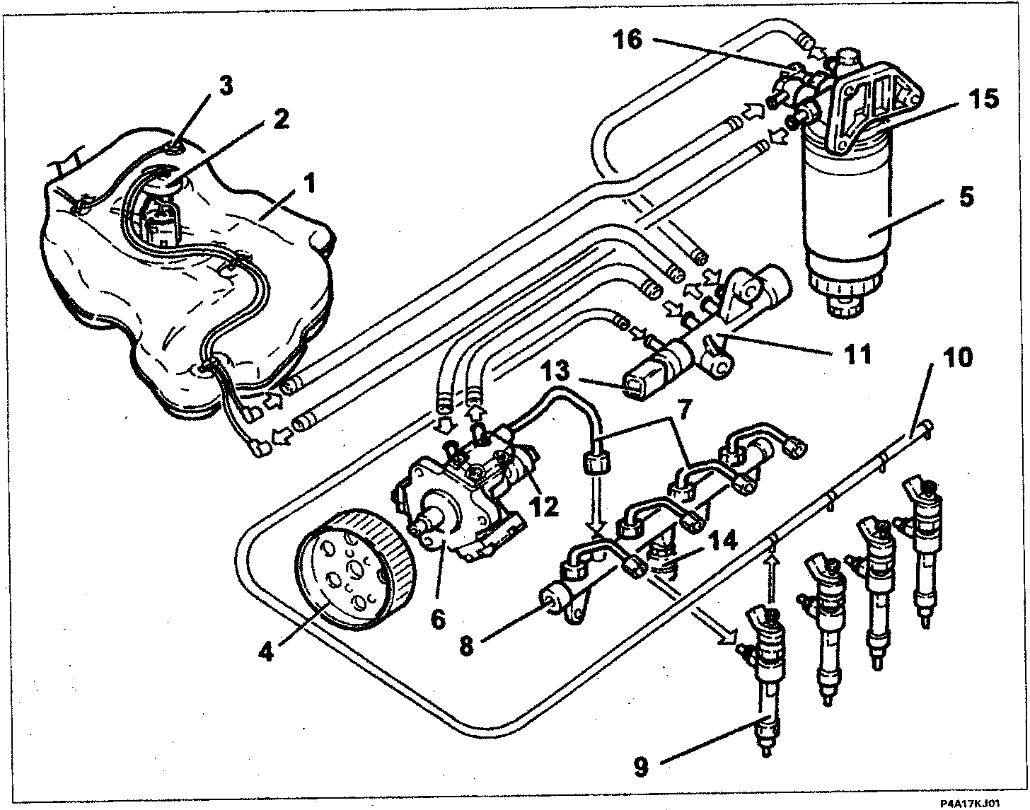
- Fuel tank
- Immersed (auxiliary) electric pump assembly complete with fuel gauge
- Multi-purpose valve
- Pressure pump drive pulley
- Diesel filter cartridge
- Pressure-pump
- High pressure pipes
- Supply manifold (rail)
- Injectors
- Fuel recirculation pipe (return for the injectors)
- Return manifold
- Pressure regulator
- Fuel temperature sensor
- Fuel pressure sensor
- Diesel heater
- Thermal switch
Parts & tools for this job For 1995 Fiat Bravo
- TOOLOBD2 scannerSearch: OBD2 scanner
- TOOLDigital multimeterSearch: automotive digital multimeter
- TOOLBack-probe test leadsSearch: back probe test leads
Links open Amazon search results in a new tab. As an Amazon Associate I earn from qualifying purchases.