
Control panel - r+r
- Make
- Fiat
- Model
- Croma Factory Service Manual
- Year
- 2005–2010
- Section
- Instruments › Control panel - r+r
CONTROL PANEL - R+R
Removing
- Turn the ignition key to the OFF position.
- Open the bonnet.
- Disconnect the negative battery terminal.
| Description | Connector | |
|---|---|---|
| BATTERY | See A001 BATTERY |
Op. 7040A26 STEERING COLUMN TRIM - R+R
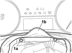
1. Unscrew and recover bolts (1a) from the control panel junction trim (1b), then remove the trim.
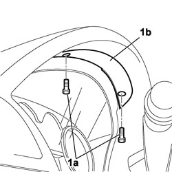
1. Unscrew bolts (1a) securing the retaining panel (1b) and partly prise up the control panel from the facia to gain access to the electrical connection.
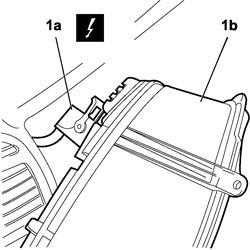
1. Disconnect electrical connection (1a) and remove the control panel (1b) from the facia.
| Description | Connector | |
|---|---|---|
| 1a | INSTRUMENT PANEL | See E050 INSTRUMENT PANEL |
The control panel cannot be disassembled. It can only be removed and refitted to the vehicle.
Refitting
Several of the CAN nodes, including the instrument panel, are programmed with default settings that the customer will find when they acquire the vehicle. If the panel is replaced, the Parts Dept. will send a blank component. once fitted, the data memorized in the Body Computer must be transferred to it by carrying out the "PROXY ALIGNMENT" procedure using the Examiner.
- Connect the electrical connection to the control panel.
| Description | Connector | |
|---|---|---|
| INSTRUMENT PANEL | See E050 INSTRUMENT PANEL |
- Position the control panel in its seat with the retaining panel.
- Tighten the bolts fixing it to the retaining panel.
- P osition the control panel junction trim and tighten the bolts.
Op. 7040A26 STEERING COLUMN TRIM - R+R
- Connect the negative battery terminal.
| Description | Connector | |
|---|---|---|
| BATTERY | See A001 BATTERY |
- Check the operation of the instrument panel.
Parts & tools for this job For 2005 Fiat Croma
- TOOLDigital multimeterSearch: automotive digital multimeter
- PARTAssorted fuse kitSearch: car fuse assortment kit
- TOOLWire crimper and connector kitSearch: wire crimper connector kit
Links open Amazon search results in a new tab. As an Amazon Associate I earn from qualifying purchases.