
Fuel line from manifolds - r r
- Make
- Fiat
- Model
- Doblò Factory Service Manual
- Year
- 2000–2010
- Section
- Fuel tank and pipes › Fuel line from manifolds - r r
Fuel line from manifolds - r r
Removing
Ensure that the ignition key is in the OFF position, then disconnect the negative battery terminal.
| Name | Connector | |
|---|---|---|
| Battery | A1 |
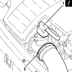
1. Disconnect the electrical connection from the air flow meter.
| Name | Connector | |
|---|---|---|
| 1 | Air flow meter | K41 |
2. Loosen the band and disconnect the the turbocharger air inlet sleeve from the rigid pipe, air flow meter side.
Removing
Position the vehicle on the ramp.
Proceed with the removal - 5530B10 battery - r+r.
Proceed with the removal - 5530B52 Battery DRIP TRAY/SUPPORT - R.R..
Proceed with the removal - 1044B10 fuel filter assembly - r + r or replace.
Proceed with the removal - 3330D24 vacuum pipe for brake servo - r+r.
Proceed with the removal - 7210E22 R.R. WINDSCREEN BASE TRIM.
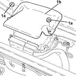
1. Undo the nuts (1a) and remove the protection (1b).
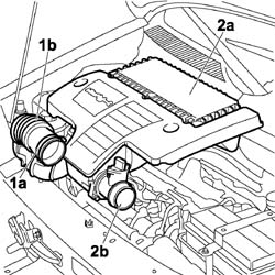
1. Loosen the band (1a) and disconnect the flexible hose (1b) from the air intake.
2. Remove the air filter (2a) complete with air flow meter (2b) by releasing from the underlying pins and then from the rear fastening.
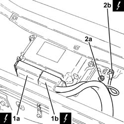
1. Disconnect the electrical connections (1a) and (1b) from the diesel electronic injection system control unit.
| Name | Connector | |
|---|---|---|
| 1a | Engine management ECU | M10A |
| Name | Connector | |
|---|---|---|
| 1b | Engine management ECU | M10B |
2. Undo nut (2a) and disconnect earth lead (2b).
| Name | Connector | |
|---|---|---|
| 2b | Earth on engine | C60 |
Undo the fuel filler cap and remove it to discharge the pressure in the system.
1. Disconnect the quick-release connector for the front fuel return pipe, fuel filter side.
2. Disconnect the rapid attachment for the front fuel return pipe, rear fuel return pipe side.
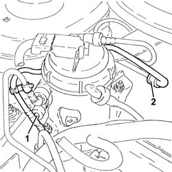
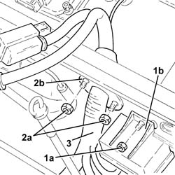
1. Undo the nut (1a) and move the plug preheating control unit (1b) aside without disconnecting the electrical wiring.
2. Undo the nuts (2a) securing the cable pass (2b).
3. Withdraw the wiring complete with electrical connections from the engine bulkhead.
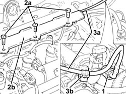
1. Disconnect the rapid attachment on the front fuel return pipe, single fuel manifold pipe side.
2. Undo the bolts (2a) and open the pipe passage channel (2b).
3. Remove the front fuel return pipe (3a) after releasing it from the bands (3b).
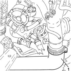
1. Loosen the band and disconnect the air supply hose from the heat exchanger to the inlet manifold, throttle body side.
Refitting
Place the front fuel return pipe back in its housing and fix it using the bands.
Close the pipe passage channel and secure it with the bolts.
Connect the rapid connector for the front fuel return pipe, rear fuel return pipe side.
Connect the quick-release connector for the front fuel supply pipe, fuel filter side.
Connect the rapid attachment of the front fuel return pipe, single fuel manifold pipe side.
Fit the air filter complete with air flow meter in its seating, engaging it in the rear attachment and then in the underlying pins.
Connect the flexible hose to the air intake on the crossmember and tighten the fixing band.
Connect the air intake sleeve to the turbocharger, air flow meter side, and tighten the band.
Connect the electrical connection to the air flow meter.
| Name | Connector | |
|---|---|---|
| Air flow meter | K41 |
Connect the battery negative terminal.
| Name | Connector | |
|---|---|---|
| Battery | A1 |
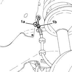
1. Remove the clip (1a) and undo the connector of the rigid pipe from master cylinder to front right brake (1b), flexible pipe side.
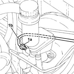
1. Undo the connector (1a) and disconnect the rigid pipe from master cylinder to front right brake (1b), master cylinder side.
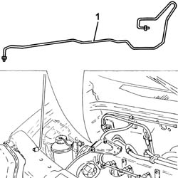
1. Remove the rigid pipe from master cylinder to front right brake after releasing it from its fixings.
Drain the air conditioning system - 5040A10 Air conditioning refrigerant CIRCUIT - Draining and Refilling.
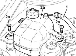
1. Loosen the band and disconnect the coolant return pipe from the engine coolant supply reservoir.
2. Undo the bolts (2a) and move the engine cooling reservoir (2b).
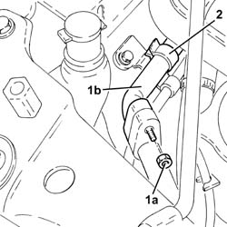
1. Undo the nut (1a) and disconnect the pipe from evaporator to compressor inlet pipe (1b), compressor inlet pipe side.
Seal the disconnected connectors, using suitable plugs, to prevent humidity and impurities from entering the system.
2. Release the pipe from evaporator to compressor inlet pipe from the fixing band.
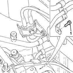
1. Undo the bolt on the bracket securing the air conditioning pipes to the bodyshell.
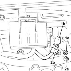
1. Undo the nut (1a) and disconnect the pipe from evaporator to compressor inlet pipe (1b), expansion valve side.
2. Undo the nut (2a) and disconnect the pipe from the dehydrating filter to the expansion valve (2b), expansion valve side.
Seal the disconnected connectors, using suitable plugs, to prevent humidity and impurities from entering the system.
1. Remove the pipe from evaporator to compressor inlet pipe.
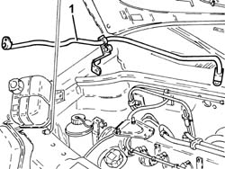
1. Undo the bolts on the bracket securing the fuel pipes to the bodyshell.
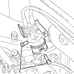
1. Disconnect the rapid attachment on the front fuel return pipe from the fuel return manifold pipe.
2. Release the fuel pipes from the fixings on the wing and engine compartment bulkhead.
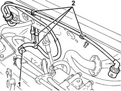
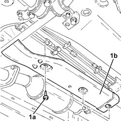
Proceed with the removal - 7055B54 under-engine guard - r r.
1. Undo the fixings (1a) and remove the fuel pipes protection (1b).
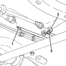
1. Disconnect the rapid attachment for the front fuel supply pipe to the intermediate one.
2. Disconnect the rapid attachment of the front fuel return pipe to the intermediate one.
3. Release the front fuel supply/return pipes from the fixings on the under the bodyshell.
1. Withdraw and remove the front fuel return pipe.
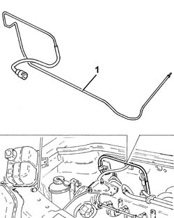
Refitting
Refit the front fuel return pipe in its seating.
Secure the front fuel supply/return pipes to the fixing under the bodyshell.
Connect the rapid attachment of the front fuel return pipe to the intermediate one.
Connect the rapid attachment of the front fuel supply pipe to the intermediate one.
Refit the fuel pipes protection in its seating and secure it with the fixings.
Proceed with the refitting - 7055B54 under-engine guard - r r.
Secure the fuel pipes to the fixings on the wing and engine bulkhead.
Connect the rapid attachment of the front fuel return pipe from the fuel return manifold pipe.
Tighten the bolts on the bracket securing the fuel pipes to the bodyshell.
Refit in its seating the pipe from evaporator to compressor inlet pipe.
1. Connect the pipe from dehydrating filter to expansion valve (1a), expansion valve side, and tighten the nut (1b) to the specified torque.
Replace the O-Ring seals for the connectors. Only use green coloured seals, resistant to R134A coolant fluid. Lubricate the threads of the connectors using anti-freeze.
| Fastening | Component | Ø | Value (daNm) | |
|---|---|---|---|---|
| 1b | Nut | PIPE FRM FILTER/DEHYDRATOR TO EXPAN VALV | M6 | (Expansion valve side) 0.7 ÷ 1.1 |
2. Connect the pipe from evaporator to compressor inlet pipe (2a), expansion valve side, and tighten the nut (2b) to the specified torque.
Replace the O-Ring seals for the connectors. Only use green coloured seals, resistant to R134A coolant fluid. Lubricate the threads of the connectors using anti-freeze.
| Fastening | Component | Ø | Value (daNm) | |
|---|---|---|---|---|
| 2b | Nut | PIPE FROM EVAPORATOR | M6 | (Expansion valve side) 0.7 ÷ 1.1 |
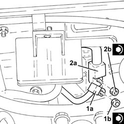
Tighten the bolt on the bracket securing the air conditioning pipes to the bodyshell.
1. Secure the pipe from evaporator to compressor inlet pipe to the fixing band.
2. Connect the pipe from evaporator to compressor inlet pipe (2a), compressor inlet pipe side, and tighten the nut (2b) to the specified torque.
Replace the O-Ring seals for the connectors. Only use green coloured seals, resistant to R134A coolant fluid. Lubricate the threads of the connectors using anti-freeze.
| Fastening | Component | Ø | Value (daNm) | |
|---|---|---|---|---|
| 2b | Nut | PIPE FROM EVAPORATOR | M6 | (Compressor inlet pipe side) 0.7 ÷ 1.1 |
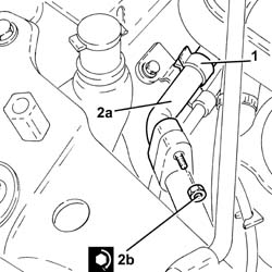
Refit the coolant reservoir in its seating and secure with its bolt.
Connect the coolant return pipe to the engine coolant supply reservoir and tighten the relevant band.
Refit in its seating the rigid pipe from master cylinder to front right brake and secure it.
1. Connect the rigid pipe from master cylinder to front right brake (1a), master cylinder side, and tighten the connector (1b) to the specified torque.
| Fastening | Component | Ø | Value (daNm) | |
|---|---|---|---|---|
| 1b | Connector | RIGID PIPE TO FRONT BRAKES | M10 | (Master cylinder side) 1.3 ÷ 1.5 |
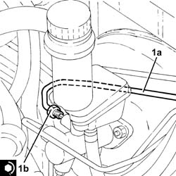
1. Tighten the connector on the rigid pipe from master cylinder to front right brake (1a), flexible pipe side, and secure it with the clip (1b).
| Fastening | Component | Ø | Value (daNm) | |
|---|---|---|---|---|
| 1a | Connector | RIGID PIPE TO FRONT BRAKES | M10 | (Flexible pipe side) 1.3 ÷ 1.5 |
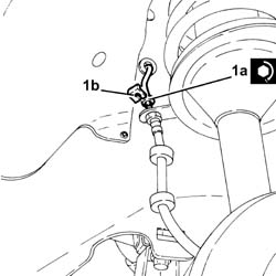
Connect the air supply hose from the heat exchanger to the inlet manifold, throttle body side, and tighten the band.
Fit the wiring complete with electrical connections for the diesel electronic fuel injection control unit through the passage on the engine bulkhead.
Tighten the cable pass nuts.
Connect the earth lead and fix it using the nut.
Connect the electrical connections to the diesel electronic injection control unit.
Place the protection back in its housing and fix it using the nuts.
Proceed with the refitting - 7210E22 R.R. WINDSCREEN BASE TRIM.
Place the plug preheating control unit back in its housing and secure with the relevant nut.
Proceed with the refitting - 3330D24 vacuum pipe for brake servo - r+r.
Proceed with the refitting - 1044B10 fuel filter assembly - r + r or replace.
Proceed with the refitting - 5530B52 Battery DRIP TRAY/SUPPORT - R.R..
Proceed with the refitting - 5530B10 battery - r+r.
Refill the air condiitoning system - 5040A10 Air conditioning refrigerant CIRCUIT - Draining and Refilling.
Remove the car from the ramp.
Parts & tools for this job For 2000 Fiat Doblò
- PARTEngine gasket setSearch: Fiat Doblò 2000 engine gasket set
- TOOLTorque wrenchSearch: 3/8 inch torque wrench
- TOOLFeeler gauge setSearch: feeler gauge set
Links open Amazon search results in a new tab. As an Amazon Associate I earn from qualifying purchases.