
Diesel injection wiring harness - r r
- Make
- Fiat
- Model
- Idea Factory Service Manual
- Year
- 2003–2012
- Section
- Diesel fuel injection › Diesel injection wiring harness - r r
Diesel injection wiring harness - r r
Removing
Position the vehicle on the ramp
Proceed with removal - 5530B10 battery - r+r
Proceed with removal - 5530B52 Battery DRIP TRAY/SUPPORT - R.R.
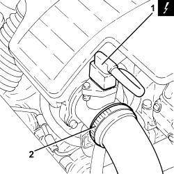
1. Disconnect the electrical connection from the air flow meter.
| Name | Connector | |
|---|---|---|
| 1 | Air flow meter | K41 |
2. Loosen the band and disconnect the the turbocharger air inlet sleeve from the rigid pipe, air flow meter side.
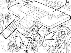
1. Remove the air filter (1a) complete with air flow meter (1b) by releasing from the underlying pins and then from the rear fastenings.
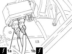
1. Disconnect the electrical connections (1a) and (1b) from the heater plugs control unit.
| Name | Connector | |
|---|---|---|
| 1a | Plug preheating control unit | M15 |
| Name | Connector | |
|---|---|---|
| 1b | Plug preheating control unit | M15 |
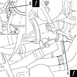
1. Disconnect the electrical connection from the engine coolant temperature sensor.
| Name | Connector | |
|---|---|---|
| 1 | Engine temperature sender unit | K36 |
2. Disconnect the electrical connection for the rpm sensor.
| Name | Connector | |
|---|---|---|
| 2 | Rpm sensor | K46 |
1. Disconnect the electrical connection from the engine oil pressure warning light switch.
| Name | Connector | |
|---|---|---|
| 1 | Engine oil pressure sensor (switch) | K30 |
2. Disconnect the electrical connections from the heater plugs.
| Name | Connector | |
|---|---|---|
| 2 | Heater plug | A40 |
3. Disconnect the electrical connections from the injectors.
| Name | Connector | |
|---|---|---|
| 3 | Injector | N70 |
4. Disconnect the electrical connection from the cam angle sensor.
| Name | Connector | |
|---|---|---|
| 4 | Timing sensor. | K47 |
5. Disconnect the electrical connection from the air conditioning compressor engagement electromagnet.
| Name | Connector | |
|---|---|---|
| 5 | Air conditioning compressor engagement electro-magnet | L20 |
6. Undo the bolts securing the cable pass to the cylinder head.
7. Release the system cable loom (7a) from the attachments (7b) and move it aside.
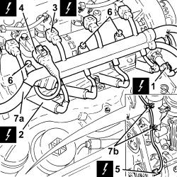
1. Disconnect the electrical connection from the fuel pressure regulator.
| Name | Connector | |
|---|---|---|
| 1 | Fuel pressure regulator | N77 |
2. Disconnect the electrical connection from the E.G.R. valve.
| Name | Connector | |
|---|---|---|
| 2 | EGR solenoid | L30 |
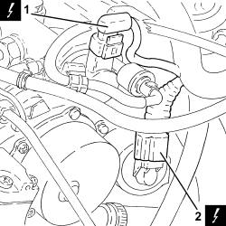
1. Disconnect the electrical connection from the fuel pressure sensor.
| Name | Connector | |
|---|---|---|
| 1 | Fuel pressure sensor | K83 |
2. Disconnect the electrical connection from the excess pressure sensor.
| Name | Connector | |
|---|---|---|
| 2 | Turbocharging sensor | K82 |
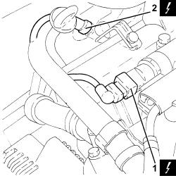
1. Disconnect the electrical connections (1a) and (1b) from the diesel electronic injection system control unit.
| Name | Connector | |
|---|---|---|
| 1a | Engine management control unit | M10A |
| Name | Connector | |
|---|---|---|
| 1b | Engine management control unit | M10B |
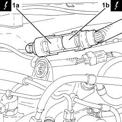
Proceed with removal
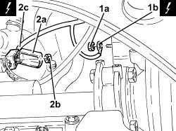
1. Undo the nut (1a) and disconnect the electrical connection (1b) from the alternator.
| Name | Connector | |
|---|---|---|
| 1b | Alternator | A10 |
2. Open the protective cover (2a), undo the nut (2b) and disconnect the electrical connection (2c) from the starter motor.
| Name | Connector | |
|---|---|---|
| 2c | Starter motor | A20 |
Release the cable loom from the bands securing it to the air chamber and remove it.
Refitting
Refit in its seating the system cable loom and secure it to the bands on the air chamber.
Connect the electrical connection to the starter motor, secure it with the nut and close the protective cover.
Connect the electrical connection to the alternator and secure it using the nut.
Proceed with refitting.
Connect the electrical connections to the diesel electronic injection control unit.
Connect the electrical connection to the excess pressure sensor.
Connect the electrical connection to the fuel pressure senor.
Connect the electrical connection to the EGR solenoid.
Connect the electrical connection to the fuel pressure regulator.
Refit the wiring loom in its seating and secure it.
Tighten the bolts securing the cable pass to the cylinder head.
Connect the electrical connection to the air conditioner compressor electromagnet.
Connect the electrical connection to the cam angle sensor
Connect the electrical connections to the injectors.
Connect the electrical connections to the heater plugs.
Connect the electrical connection to the engine oil pressure warning light switch.
Connect the electrical connection for the rpm sensor.
Connect the electrical connection to the engine coolant temperature sensor.
Connect the electrical connections to the pre-heating control unit.
Replace the air filter, complete with air flow meter, in its housing.
Connect the air intake sleeve to the turbocharger, air flow meter side, and tighten the band.
Connect the electrical connection to the air flow meter.
Proceed with refitting - 5530B52 Battery DRIP TRAY/SUPPORT - R.R..
Proceed with refitting - 5530B10 battery - r+r.
Remove the car from the ramps.
Parts & tools for this job For 2003 Fiat Idea
- PARTGlow plugsSearch: Fiat Idea 2003 glow plugs
- TOOLGlow plug socketSearch: glow plug socket
- TOOLDiesel compression testerSearch: diesel compression tester
Links open Amazon search results in a new tab. As an Amazon Associate I earn from qualifying purchases.