
Introduction - ENGINE TURBOCHARGING SYSTEM
- Make
- Fiat
- Model
- Stilo Factory Service Manual
- Year
- 2001–2007
- Section
- Engine turbocharging system › Introduction - ENGINE TURBOCHARGING SYSTEM
Introduction - ENGINE TURBOCHARGING SYSTEM
The engine turbocharging system, managed by the electronic control unit, is made up of the following parts.
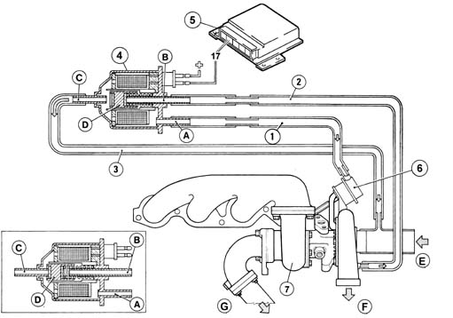
A, duct connected to the wastegate via a sleeve
B, duct, connected to the outlet side of the turbocharger via a sleeve.
C, duct, connected to the outlet side of the turbocharger via a sleeve.
D, cylinder
E, from intake filter
F, to heat exchanger
G, to exhaust
1, connection sleeve
2, connection sleeve
3, connection sleeve
4, open 3-way control solenoid (in closed box)
5, electronic control unit
6, waste-gate valve
7, turbocharger
The turbocharger control solenoid (4) is governed permanently by the injection control unit (5) via pin 17.
Control solenoid (4) is a three-way solenoid (A-B-C).
Duct A is connected via sleeve (1) to wastegate actuator (6). Duct B is connected via sleeve (2) to the turbocharger pressure relief duct.
Duct C is connected via sleeve (3) to the turbocharger intake duct.
When the solenoid is activated by the control unit, cylinder (D) is magnetised by the coil winding and begins to pulse under the control of a duty-cycle signal: cylinder pulsing frees duct (B) and closes duct (C) to allow excess pressure from the turbocharger to reach wastegate valve actuator (6) via pipe (2) and pipe (1) and modulate incoming boost pressure
Conversely, when cylinder (D) closes duct (B) and opens duct (C), the pressure that previously acted on actuator (6) is discharged through pipe (3) into the turbocharger intake duct to increase the pressure boost.
It basically consists of two impellers fitted on the same shaft, which rotates on two floating bearings which are lubricated by means of an branch off the engine lubrication system.
The oil used disperses some of the large amount of heat which is given off by the exhaust gases at the turbine.
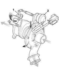
There is a wastegate valve (1) fitted on the turbocharger, controlled by a pneumatic actuator (2), which allows the passage of exhaust gases to the turbine to be choked depending on the engine's power/torque requirements.
Parts & tools for this job For 2001 Fiat Stilo
- PARTEngine gasket setSearch: Fiat Stilo 2001 engine gasket set
- TOOLTorque wrenchSearch: 3/8 inch torque wrench
- TOOLFeeler gauge setSearch: feeler gauge set
Links open Amazon search results in a new tab. As an Amazon Associate I earn from qualifying purchases.