
Variable geometry turbocharger exhaust manifold assembly sleeveleading to exhaust pipe r r
- Make
- Fiat
- Model
- Stilo Factory Service Manual
- Year
- 2001–2007
- Section
- Engine turbocharging system › Variable geometry turbocharger exhaust manifold assembly sleeveleading to exhaust pipe r r
Variable geometry turbocharger exhaust manifold assembly sleeveleading to exhaust pipe r r
Refer to op. 1064A19 TURBOCHARGER - EXHAUST MANIFOLD - EXHAUST PIPE CONNECTING HOSE - R.R.
Removing
Place the car on a lift.
- 1016A10 sound-proofing cover - r + r.
- 7055B54 under-engine guard - r r.
- 7055B42 Additional FRONT WHEEL ARCH (one), left or right - R.R.
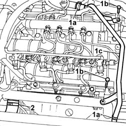
1. Disconnect both retaining bands (1a), unscrew bolts (1b), then remove the rigid section of the engine oil vapour pipe.
2. Loosen the band and disconnect the lower radiator coolant outlet hose from the radiator, water pump rigid inlet pipe end.
Recover the coolant which comes out in a suitable container.
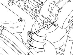
1. Loosen the band and disconnect the coolant outlet pipe from the water/exhaust gas heat exchanger for the E.G.R. system, water pump rigid coolant inlet pipe side.
2. Loosen the band and disconnect the coolant outlet pipe from the climate control heater, water pump rigid inlet pipe side.
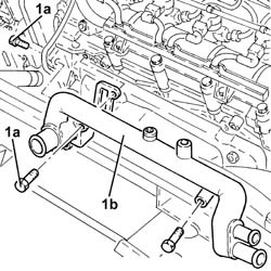
1. Undo the bolts (1a) and remove the water pump rigid inlet pipe (1b).
Remove the gasket.
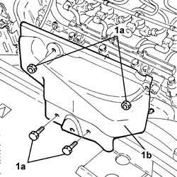
1. Undo retaining nuts and bolts (1a) and remove the upper exhaust manifold heat shield (1b).
Raise the lift.
1. Undo the retaining bolts.
2. Remove the lower exhaust manifold heat shield.
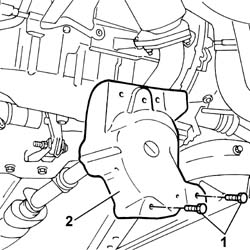
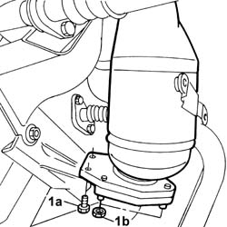
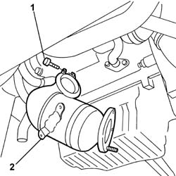
1. Unscrew the fastenings securing the catalytic preconverter to flange (1a) on the first exhaust pipe section and the reinforcement bracket (1b).
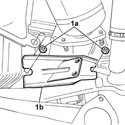
1. Unscrew nuts (1a) and remove the catalytic preconverter reinforcement bracket (1b).
1. Unscrew the EGR gas pipe bolts from the manifold.
2. Unscrew the bolt securing the metal band from the heat exchanger.
3. Remove the exhaust gas delivery pipe to the turbocharger.
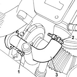
1. Undo collars (1a) to remove the air pipe from filter to turbocharger (1b).
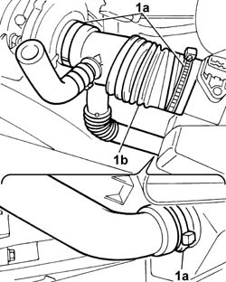
1. Disconnect the outlet pipe to the air-air intercooler from the turbocharger.
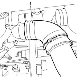
1. Unscrew the fitting and disconnect the oil delivery pipe to the turbocharger.
2. Unscrew the bolts and disconnect the oil return pipe from the turbocharger to the engine block from the seat on the engine block.
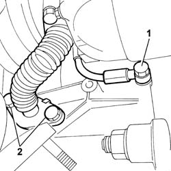
1. Disconnect the vacuum pipe from the turbocharger variable geometry control actuator.
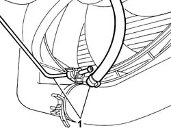
1. Loosen the collar bolt.
2. Remove the catalytic preconverter.
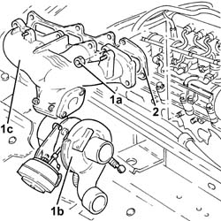
1. Undo the nuts (1a) and remove the variable geometry turbocharger assembly (1b) complete with exhaust manifold (1c).
2. Remove the exhaust manifold gasket.
Refitting
Fit the new exhaust manifold gasket in its seat on the cylinder head.
Fit the turbocharger- exhaust manifold assembly.
Tighten the nuts securing the exhaust manifold to the cylinder head to the recommended torque.
| Fastening | Component | Ø | Value (daNm) | |
|---|---|---|---|---|
| Nut | EXHAUST MANIFOLD/S | M8 | 2.5 |
Fit the catalytic preconverter into its seat on the turbocharger.
Tighten the bolt securing the collar joining the preconverter-turbocharger to torque.
| Fastening | Component | Ø | Value (daNm) | |
|---|---|---|---|---|
| Bolt | CATALYTIC PRE-CONVERTER | M10 | 2.5 |
Connect the vacuum pipe from the turbocharger variable geometry control actuator.
Connect the engine oil delivery pipe to the turbocharger, crankcase side, and tighten the connector to the recommended torque.
| Fastening | Component | Ø | Value (daNm) | |
|---|---|---|---|---|
| Connector | OIL DELIVERY PIPE TO TURBO | M12 | 1.5 |
Tighten the bolt fixing the enigne oil return pipe from the turbocharger, engine crankcase side.
| Fastening | Component | Ø | Value (daNm) | |
|---|---|---|---|---|
| Bolt | OIL RETURN PIPE FROM TURBO | M8 | 2.5 |
Connec the air-air intercooler outlet pipe to the turbocharger.
Fit the air filter union pipe to the turbocharger and secure using the collars.
Place the E.G.R. system water/exhaust gas heat exchanger exhaust gas inlet pipe back in its housing and tighten the band.
Tighten the bolts fixing the exhaust gas inlet pipe to the water/exhaust gas heat exchanger for the E.G.R. system, exhaust manifold side to the recommended torque.
Fit the catalytic preconverter reinforcement bracket and tighten the nuts securing it to the engine block.
| Fastening | Component | Ø | Value (daNm) | |
|---|---|---|---|---|
| Nut | PRECONVERTER MOUNTING BRACKET | M8 | (Oil sump) 2.5 |
Tighten the bolts securing the preconverter to the bracket to torque.
| Fastening | Component | Ø | Value (daNm) | |
|---|---|---|---|---|
| Bolt | CATALYTIC PRE-CONVERTER | M8 | (Mounting bracket) 2.5 |
Tighten the nuts securing the preconverter to the front section of the exhaust pipe to torque.
| Fastening | Component | Ø | Value (daNm) | |
|---|---|---|---|---|
| Nut | EXHAUST PIPE TO ENGINE | M8 | (Catalytic pre-converter) 2.5 |
Fit the catalytic converter heat shield and tighten the lower retaining bolts to torque.
| Fastening | Component | Ø | Value (daNm) | |
|---|---|---|---|---|
| Bolt | LH MANIFOLD HEAT SHIELD BULKHEAD | M6 | 0.9 |
Lower the lift.
Fit the exhaust manifold heat shield and tighten the retaining bolts.
| Fastening | Component | Ø | Value (daNm) | |
|---|---|---|---|---|
| Nut | LH MANIFOLD HEAT SHIELD BULKHEAD | M6 | 0.9 |
Fit the water pump rigid coolant inlet pipe complete with a new gasket and fix it tightening the bolts to the recommended torque.
| Fastening | Component | Ø | Value (daNm) | |
|---|---|---|---|---|
| Bolt | COOLANT PUMP RIGID INLET PIPE | M6 | 0.9 |
Connect the coolant return hose from the climate control heater on the side of the rigid inlet pipe to the water pump and do up the band.
Connect the coolant outlet pipe from the E.G.R. system water/exhaust gas heat exchanger to the water pump rigid inlet pipe and tighten the band.
Connect the lower radiator coolant outlet hose to the water pump rigid inlet pipe and tighten the band.
Connect the rigid section of the engine oil vapour pipe and secure with two collars. Also secure with bolts.
- 7055B42 Additional FRONT WHEEL ARCH (one), left or right - R.R.
- 7055B54 under-engine guard - r r.
Parts & tools for this job For 2001 Fiat Stilo
- PARTExhaust gasketSearch: Fiat Stilo 2001 exhaust gasket
- TOOLPenetrating oilSearch: penetrating oil
- TOOLOBD2 scannerSearch: OBD2 scanner
Links open Amazon search results in a new tab. As an Amazon Associate I earn from qualifying purchases.