
FUEL TANK - R.R. and decant fuel
- Make
- Lancia
- Model
- Thesis Factory Service Manual
- Year
- 2002–2009
- Section
- Fuel tank and pipes › FUEL TANK - R.R. and decant fuel
FUEL TANK - R.R. and decant fuel
Removing
- Position the vehicle on a lift.
- Draw off the fuel from the tank using a suitable tool and protection in line with current safety regulations.
- Open the boot, remove the cover on the left hand side and disconnect the negative battery lead.
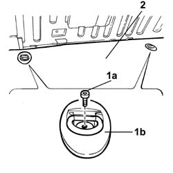
1. Undo the bolts (1a) and remove the hooks (1b).
2. Remove the luggage compartment cover.
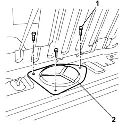
1. Undo the fixing bolts.
2. Remove the access cover for the submerged fuel assembly complete with level gauge control.
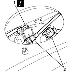
1. Disconnect the electrical connection from the submerged pump assembly complete with level gauge.
| Description | Connector | |
|---|---|---|
| 1 | Fuel pump and level gauge | N040 |
2. Disconnect the rapid connector for the fuel supply and return pipe from the submereged pump assembly complete with level gauge.
See in Op. 4450B13 Rear WHEELS (two) - R.R.
See in Op. 7055B45 Right rear wheel arch liner - R.R.
See in Op. 4420A35 Rear suspension SHOCK ABSORBERS - R.R.
See in Op. 1076B20
See in Op. 4420D10 REAR SUSPENSION AXLE - R.R.
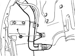
1. Undo the bolts fixing the fuel filler pipe to the bodyshell.
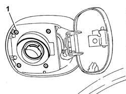
1. Undo the nut fixing the fuel filler pipe to the bodyshell.
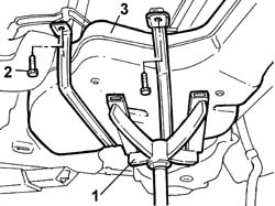
1. Position a suitable tool under the tank to support it during the removal operation.
2. Undo the bolts fixing the tank brackets.
- Lower the hydraulic jack.
3. Remove the fuel tank complete with fuel filler pipe.
Refitting
- Position the fuel tank on the supporting equipment.
- Raise the tank and tighten the bolts fixing the tank to the bodyshell to torque.
| Value - daNm | Fastening | Component | Ø | |
|---|---|---|---|---|
| 1.2 | Bolt | FUEL TANK | M8 |
- Remove the tank supporting equipment.
- Tighten the bolts fixing the fuel filler pipe to the bodyshell.
- Tighten the nut fixing the fuel filler pipe to the bodyshell.
See in Op. 4420D10 REAR SUSPENSION AXLE - R.R.
See in Op. 1076B20
See in Op. 4420A35 Rear suspension SHOCK ABSORBERS - R.R.
See in Op. 7055B45 Right rear wheel arch liner - R.R.
See in Op. 4450B13 Rear WHEELS (two) - R.R.
- Connect the rapid connectors for the fuel supply and return pipes on the pump.
- Connect the electrical connection to the submerged pump assembly complete with level gauge.
| Description | Connector | |
|---|---|---|
| Fuel pump and level gauge | N040 |
- Fit the access cover and secure it using the bolts.
- Fit the luggage compartment cover and secure it using the bolts.
- Open the boot, connect the negative battery lead and fit the cover on the left hand side.
- Remove the vehicle from the lift.
Removing
- Position the vehicle on a lift.
- Draw off the fuel from the tank using a suitable tool and protection in line with current safety regulations.
- Open the boot, remove the cover on the left hand side and disconnect the negative battery lead.
1. Undo the bolts (1a) and remove the hooks (1b).
2. Remove the luggage compartment cover.
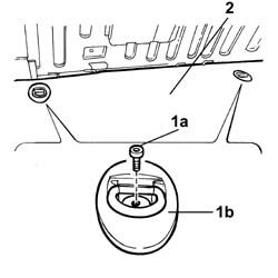
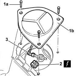
1. Undo the bolts (1a) and remove the access cover (1b) for the submerged pump assembly complete with level gauge.
2. Disconnect the electrical connection from the submerged pump assembly complete with level gauge.
| Description | Connector | |
|---|---|---|
| 2 | Fuel pump and level gauge | N040 |
3. Disconnect the rapid connector for the fuel supply pipe from the submereged pump assembly complete with level gauge.
See in Op. 4450B13 Rear WHEELS (two) - R.R.
See in Op. 7055B45 Right rear wheel arch liner - R.R.
See in Op. 4420A35 Rear suspension SHOCK ABSORBERS - R.R.
See in Op. 1076B20 Rear exhaust SILENCER - R.R.
See in Op. 4420D10 REAR SUSPENSION AXLE - R.R.
1. Undo the bolts fixing the fuel filler pipe to the bodyshell.
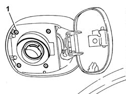
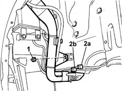
1. Undo the nut fixing the fuel filler pipe to the bodyshell.
2. Disconnect the anti-evaporation system pipes from the rapid connectors (2a) and (2b).
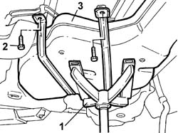
1. Position a suitable tool under the tank to support it during the removal operation.
2. Undo the bolts fixing the tank brackets.
- Lower the hydraulic jack.
3. Remove the fuel tank complete with fuel filler pipe.
Refitting
- Position the fuel tank on the supporting equipment.
- Raise the tank and tighten the bolts fixing the tank to the bodyshell to torque.
| Value - daNm | Fastening | Component | Ø | |
|---|---|---|---|---|
| 1.2 | Bolt | FUEL TANK | M8 |
- Remove the tank supporting equipment.
- Connect the anti-evaporation pipes connected to the vapour separator to the rapid connectors.
- Tighten the bolts fixing the fuel filler pipe to the bodyshell.
- Tighten the nut fixing the fuel filler pipe to the bodyshell.
See in Op. 4420D10 REAR SUSPENSION AXLE - R.R.
See in Op. 1076B20 Rear exhaust SILENCER - R.R.
See in Op. 4420A35 Rear suspension SHOCK ABSORBERS - R.R.
See in Op. 7055B45 Right rear wheel arch liner - R.R.
See in Op. 4450B13 Rear WHEELS (two) - R.R.
- Connect the fuel supply pipe rapid connector.
- Connect the electrical connection to the submerged pump assembly complete with level gauge.
| Description | Connector | |
|---|---|---|
| Fuel pump and level gauge | N040 |
- Fit the access cover and secure it using the bolts.
- Fit the luggage compartment cover and secure it using the bolts.
- Open the boot, connect the negative battery lead and fit the cover on the left hand side.
- Remove the vehicle from the lift.
Removing
- Position the vehicle on a lift.
- Draw off the fuel from the tank using a suitable tool and protection in line with current safety regulations.
- Open the boot, remove the cover on the left hand side and disconnect the negative battery lead.
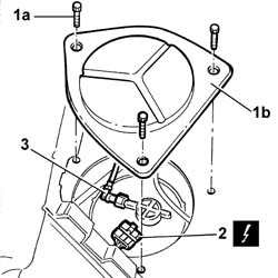
1. Undo the bolts (1a) and remove the hooks (1b).
2. Remove the luggage compartment cover
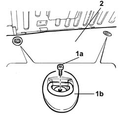
1. Undo the bolts (1a) and remove the access cover (1b) for the submerged pump assembly complete with level gauge.
2. Disconnect the electrical connection from the submerged pump assembly complete with level gauge.
| Description | Connector | |
|---|---|---|
| 2 | Fuel pump and level gauge | N040 |
3. Disconnect the rapid connector for the fuel supply pipe from the submereged pump assembly complete with level gauge.
See in Op. 4450B13 Rear WHEELS (two) - R.R.
See in Op. 7055B45 Right rear wheel arch liner - R.R.
See in Op. 4420A35 Rear suspension SHOCK ABSORBERS - R.R.
See in Op. 1076B20 Rear exhaust SILENCER - R.R.
See in Op. 4420D10 REAR SUSPENSION AXLE - R.R.
1. Undo the bolts fixing the fuel filler pipe to the bodyshell.
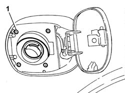
1. Undo the nut fixing the fuel filler pipe to the bodyshell.
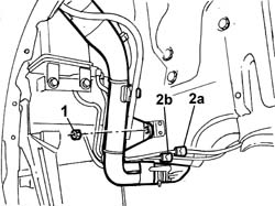
2. Disconnect the anti-evaporation system pipes from the rapid connectors (2a) and (2b).
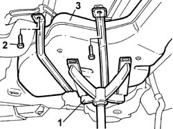
1. Position a suitable tool under the tank to support it during the removal operation.
2. Undo the bolts fixing the tank brackets.
- Lower the hydraulic jack.
3. Remove the fuel tank complete with fuel filler pipe.
Refitting
- Position the fuel tank on the supporting equipment.
- Raise the tank and tighten the bolts fixing the tank to the bodyshell to torque.
| Value - daNm | Fastening | Component | Ø | |
|---|---|---|---|---|
| 1.2 | Bolt | FUEL TANK | M8 |
- Remove the tank supporting equipment.
- Connect the anti-evaporation pipes connected to the vapour separator to the rapid connectors.
- Tighten the bolts fixing the fuel filler pipe to the bodyshell.
- Tighten the nut fixing the fuel filler pipe to the bodyshell.
See in Op. 4420D10 REAR SUSPENSION AXLE - R.R.
See in Op. 1076B20 Rear exhaust SILENCER - R.R.
- [4420A35]
See in Op. 7055B45 Right rear wheel arch liner - R.R.
See in Op. 4450B13 Rear WHEELS (two) - R.R.
- Connect the fuel supply pipe rapid connector.
- Connect the electrical connection to the submerged pump assembly complete with level gauge.
| Description | Connector | |
|---|---|---|
| Fuel pump and level gauge | N040 |
- Fit the access cover and secure it using the bolts.
- Fit the luggage compartment cover and secure it using the bolts.
- Open the boot, connect the negative battery lead and fit the cover on the left hand side.
- Remove the vehicle from the lift.
Removing
- Position the vehicle on a lift.
- Draw off the fuel from the tank using a suitable tool and protection in line with current safety regulations.
- Open the boot, remove the cover on the left hand side and disconnect the negative battery lead.
1. Undo the bolts (1a) and remove the hooks (1b).
2. Remove the luggage compartment cover.
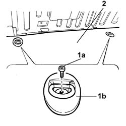
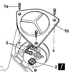
1. Undo the bolts (1a) and remove the access cover (1b) for the submerged pump assembly complete with level gauge.
2. Disconnect the electrical connection from the submerged pump assembly complete with level gauge.
| Description | Connector | |
|---|---|---|
| 2 | Fuel pump and level gauge | N040 |
3. Disconnect the rapid connector for the fuel supply and return pipe from the submereged pump assembly complete with level gauge.
See in Op. 4450B13 Rear WHEELS (two) - R.R.
See in Op. 7055B45 Right rear wheel arch liner - R.R.
See in Op. 4420A35 Rear suspension SHOCK ABSORBERS - R.R.
See in Op. 1076B20 Rear exhaust SILENCER - R.R.
See in Op. 4420D10 REAR SUSPENSION AXLE - R.R.
1. Undo the bolts fixing the fuel filler pipe to the bodyshell.
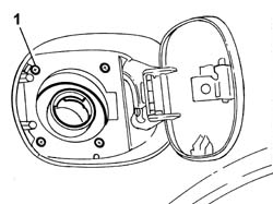
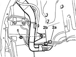
1. Undo the nut fixing the fuel filler pipe to the bodyshell.
2. Disconnect the anti-evaporation system pipes from the rapid connectors (2a) and (2b).
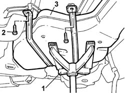
1. Position a suitable tool under the tank to support it during the removal operation.
2. Undo the bolts fixing the tank brackets.
- Lower the hydraulic jack.
3. Remove the fuel tank complete with fuel filler pipe.
Refitting
- Position the fuel tank on the supporting equipment.
- Raise the tank and tighten the bolts fixing the tank to the bodyshell to torque.
| Value - daNm | Fastening | Component | Ø | |
|---|---|---|---|---|
| 1.2 | Bolt | FUEL TANK | M8 |
- Remove the tank supporting equipment.
- Connect the anti-evaporation pipes connected to the vapour separator to the rapid connectors.
- Tighten the bolts fixing the fuel filler pipe to the bodyshell.
- Tighten the nut fixing the fuel filler pipe to the bodyshell.
See in Op. 4420D10 REAR SUSPENSION AXLE - R.R.
See in Op. 1076B20 Rear exhaust SILENCER - R.R.
See in Op. 4420A35 Rear suspension SHOCK ABSORBERS - R.R.
See in Op. 7055B45 Right rear wheel arch liner - R.R.
See in Op. 4450B13 Rear WHEELS (two) - R.R.
- Connect the fuel supply and return pipe rapid connector.
- Connect the electrical connection to the submerged pump assembly complete with level gauge.
| Description | Connector | |
|---|---|---|
| Fuel pump and level gauge | N040 |
- Fit the access cover and secure it using the bolts.
- Fit the luggage compartment cover and secure it using the bolts.
- Open the boot, connect the negative battery lead and fit the cover on the left hand side.
- Remove the vehicle from the lift.
Removing
- Position the vehicle on a lift.
- Draw off the fuel from the tank using a suitable tool and protection in line with current safety regulations.
- Open the boot, remove the cover on the left hand side and disconnect the negative battery lead.
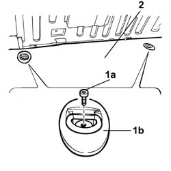
1. Undo the bolts (1a) and remove the hooks (1b).
2. Remove the luggage compartment cover.
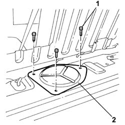
1. Undo the retaining bolts.
2. Remove the access cover for the submerged fuel assembly complete with level gauge control.
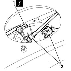
1. Disconnect the electrical connection from the submerged pump assembly complete with level gauge.
| Description | Connector | |
|---|---|---|
| 1 | Fuel pump and level gauge | N040 |
2. Disconnect the rapid connector for the fuel supply and return pipe from the submereged pump assembly complete with level gauge.
See in Op. 7040B10 LOAD CARRYING COMPARTMENT LINING - R.R.
See in Op. 7040B17 Luggage compartment/load platform side trim flap (one) - Replace
See in Op. 7040B13 Luggage compartment/load platform SIDE LINING - R.R.
See in Op. 4450B11 Rear WHEEL (one) - R.R.
See in Op. 7055B43 REAR WHEEL ARCH LINER (one), left or right - R.R.
See in Op. 4440K31 LEFT OR RIGHT REAR INTELLIGENT SUSPENSION SHOCK ABSORBER (ONE) - R.R.
See in Op. 1076B20 Rear exhaust SILENCER - R.R.
See in Op. 1076A40 Exhaust pipe HEAT SHIELDS - R.R.
See in Op. 4420D10 REAR SUSPENSION AXLE - R.R.
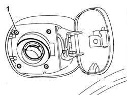
1. Undo the bolts fixing the fuel filler pipe to the bodyshell.
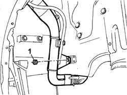
1. Undo the nut fixing the fuel filler pipe to the bodyshell.
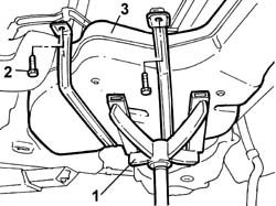
1. Position a suitable tool under the tank to support it during the removal operation.
2. Undo the bolts fixing the tank brackets.
- Lower the hydraulic jack.
3. Remove the fuel tank complete with fuel filler pipe.
Refitting
- Position the fuel tank on the supporting equipment.
- Raise the tank and tighten the bolts fixing the tank to the bodyshell to torque.
| Value - daNm | Fastening | Component | Ø | |
|---|---|---|---|---|
| 1.2 | Bolt | FUEL TANK | M8 |
- Remove the tank supporting equipment.
- Tighten the bolts fixing the fuel filler pipe to the bodyshell.
- Tighten the nut fixing the fuel filler pipe to the bodyshell.
See in Op. 4420D10 REAR SUSPENSION AXLE - R.R.
See in Op. 1076A40 Exhaust pipe HEAT SHIELDS - R.R.
See in Op. 1076B20 Rear exhaust SILENCER - R.R.
See in Op. 4440K31 LEFT OR RIGHT REAR INTELLIGENT SUSPENSION SHOCK ABSORBER (ONE) - R.R.
See in Op. 7055B43 REAR WHEEL ARCH LINER (one), left or right - R.R.
See in Op. 4450B11 Rear WHEEL (one) - R.R.
See in Op. 7040B13 Luggage compartment/load platform SIDE LINING - R.R.
See in Op. 7040B17 Luggage compartment/load platform side trim flap (one) - Replace
See in Op. 7040B10 LOAD CARRYING COMPARTMENT LINING - R.R.
- Connect the rapid connectors for the fuel supply and return pipes on the pump.
- Connect the electrical connection to the submerged pump assembly complete with level gauge.
| Description | Connector | |
|---|---|---|
| Fuel pump and level gauge | N040 |
- Fit the access cover and secure it using the bolts.
- Fit the luggage compartment cover and secure it using the bolts.
- Open the boot, connect the negative battery lead and fit the cover on the left hand side.
- Remove the vehicle from the lift.
Parts & tools for this job For 2002 Lancia Thesis
- PARTEngine gasket setSearch: Lancia Thesis 2002 engine gasket set
- TOOLTorque wrenchSearch: 3/8 inch torque wrench
- TOOLFeeler gauge setSearch: feeler gauge set
Links open Amazon search results in a new tab. As an Amazon Associate I earn from qualifying purchases.