
ENGINE - V8: DESCRIPTION AND OPERATION (page 4 of 5)
- Make
- Land Rover
- Model
- Discovery II
ENGINE - V8
DESCRIPTION AND OPERATION
12-2-9
Oil is drawn from the sump through a strainer and into the oil pump via the oil pick-up pipe. Pressurised oil from the
pump passes through the oil cooler (if fitted) mounted in front of the radiator and returns to the full flow oil filter
element. Oil from the filter passes into the main oil gallery and through internal drillings to the crankshaft where it is
directed to each main bearing and to the big-end bearings via numbers 1, 3 and 5 main bearings. An internal drilling
in the cylinder block directs oil to the camshaft where it passes through further internal drillings to the hydraulic
tappets, camshaft bearing journals and rocker shafts. Lubrication to the pistons, small ends and cylinder bores is by
oil grooves machined in the connecting rods and by splash.
Oil pressure switch
The oil pressure warning light switch registers low oil pressure in the main oil gallery on the outflow side of the filter.
Whilst the engine is running and oil pressure is correct, the switch is open. When the ignition is switched on or if oil
pressure drops below the pressure setting of the switch, the switch closes and the low oil pressure warning lamp
located in the instrument pack will illuminate.
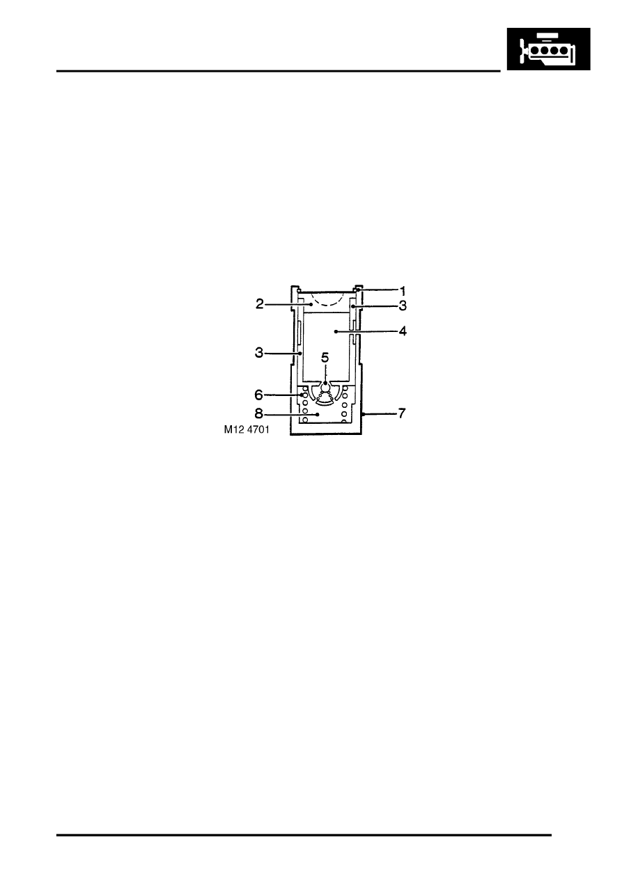
Hydraulic tappets
1 Clip
2 Pushrod seat
3 Inner sleeve
4 Upper chamber
5 Non-return ball valve
6 Spring
7 Outer sleeve
8 Lower chamber
The hydraulic tappet provides maintenance free, quiet operation of the valves. This is achieved by utilizing engine oil
pressure to eliminate the clearance between the rocker arms and valve stems. When the valve is closed, engine oil
pressure present in the upper chamber, passes through the non-return ball valve and into the lower chamber. When
the cam begins to lift the outer sleeve, the resistance of the valve spring, felt through the push rod and seat, causes
the tappet inner sleeve to move downwards inside the outer sleeve. This downwards movement closes the non-return
ball valve and increases the pressure in the lower chamber sufficiently to ensure that the valve is fully opened by the
push rod. As the tappet moves off the peak of the cam, the non-return ball valve opens thereby allowing the pressure
in both chambers to equalize. This ensures that the valve will be fully closed when the tappet is on the back of the
cam.
Crankcase ventilation
A positive crankcase ventilation system is used to vent crankcase gases to the air induction system. Gases are drawn
from the left hand rocker cover to a tapping in the throttle body. An oil separator is incorporated in the hose connection
stub pipe in the right hand rocker cover, gases from this connection are drawn to a tapping in the inlet manifold.
EMISSION CONTROL - V8, DESCRIPTION AND OPERATION, Crankcase Emission Control System.
Parts & tools for this job For Land Rover Discovery
- PARTEngine gasket setSearch: Land Rover Discovery engine gasket set
- TOOLTorque wrenchSearch: 3/8 inch torque wrench
- TOOLFeeler gauge setSearch: feeler gauge set
Links open Amazon search results in a new tab. As an Amazon Associate I earn from qualifying purchases.