
Seal - pinion gear
- Make
- Land Rover
- Model
- Freelander Workshop Manual
- Year
- 1998–2000
- Section
- Repairs › Seal - pinion gear
Transfer box - IRDSeal - pinion gear
SEAL - PINION GEAR
Service repair no - 41.29.04
- Remove pinion gear housing. See TRANSFER BOX, Repairs.
- Attach pinion housing to suitable mounting plate and secure mounting plate in vice.
NOTE: Before dismantling the pinion housing, measure turning torque on existing bearings.
- Using a torque wrench and a 30 mm socket, rotate pinion shaft 10 complete turns and record reading.
NOTE: Turning torque with NEW bearings is 180 to 200 Ncm. If the recorded figure is below the new bearing figure but above 20 to 30 Ncm, set to figure recorded. If below 20 Ncm, set to 20 to 30 Ncm.
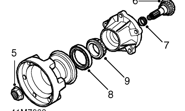
- Mark pinion flange to pinion shaft for assembly purposes.
- Hold pinion flange using LRT-51-003, remove and discard nut.
- Position pinion housing onto press, fit a suitable adaptor on end of pinion shaft, press pinion shaft from drive flange and housing.
- Remove and discard collapsible spacer from pinion shaft.
- Remove and discard pinion oil seal.
- Remove outer bearing cone from housing.
Refit
- Clean and dry pinion shaft, drive flange and housing.
- Lubricate and fit outer bearing to pinion housing.
- Lubricate new seal with IRD oil, then using a suitable adaptor, press seal into housing.
NOTE: Oil seal should be flush with end of pinion housing.
- Assemble pinion to housing using a new collapsible spacer.
- Lightly lubricate drive flange splines with Molybdenum Disulphide grease.
- Align pinion to drive flange reference marks, and press flange onto pinion shaft until a 2 mm clearance exists at the bearings.
- Fit pinion assembly to mounting plate and secure in vice.
- Fit new pinion nut, hold pinion drive flange using LRT-51-003 and tighten nut to 150 Nm. Remove LRT-51-003.
- Using the torque wrench and 30 mm socket, rotate pinion shaft 10 complete turns and measure turning torque. Turning torque limits - used bearings:
- If recorded figure is higher than 20 Ncm, set
to previously recorded figure.
- otherwise set to 20 to 30 Ncm.
Turning torque limits - new bearings:
- 180 to 200 Ncm
- If turning torque is too low, carefully tighten nut further and recheck reading. If turning torque is too high, the pinion assembly will have to be dismantled, a new collapsible spacer fitted, reassembled using a new nut and the turning torque rechecked.
- Use a Dial Test Indicator and check drive flange run-out.
NOTE: The drive flange run-out should not exceed 0.05 mm.
- Remove pinion housing from vice and mounting plate.
- Fit pinion housing to IRD. See TRANSFER BOX, Repairs.
Parts & tools for this job For 1998 Land Rover Freelander
- TOOLTorque wrenchSearch: 3/8 inch torque wrench
- TOOLSocket setSearch: socket set metric
- BOOKHaynes manualSearch: Haynes manual Land Rover Freelander
Links open Amazon search results in a new tab. As an Amazon Associate I earn from qualifying purchases.