
8.4.1. cylinder repairs
- Make
- Peugeot
- Model
- J5 Pocket Mechanic, 1.8 and 2.0 petrol
- Year
- 1987–1994
- Section
- Brake servo unit › 8.4.1. cylinder repairs
The installation of the cylinder is a reversal of the removal procedure. The nuts are tightened to 2.0 kgm (14.5 ft.bl.).
Fill the fluid reservoir with clean brake fluid and bleed the brake system as described later on.
8.4.1. CYLINDER REPAIRS
Master cylinders can be overhauled but we recommend to fit a new cylinder if the original one has developed a fault. The reservoir can be removed from the cylinder. It is just pushed into rubber grommets in the cylinder. To remove the reservoir, take a good hold of it and "rock" it to and fro, at the same time pulling it upward. The new cylinder will come with the grommets fitted and the reservoir is pushed in position. Coat the inside of the grommets with brake fluid before installation of the reservoir.
8.5. Brake Servo Unit
Repair of the brake servo unit should not be attempted. Loss of the brake servo assistance will not influence the operation of the brakes, but you will find that the pedal pressure necessary to brake the vehicle will be substantially higher.
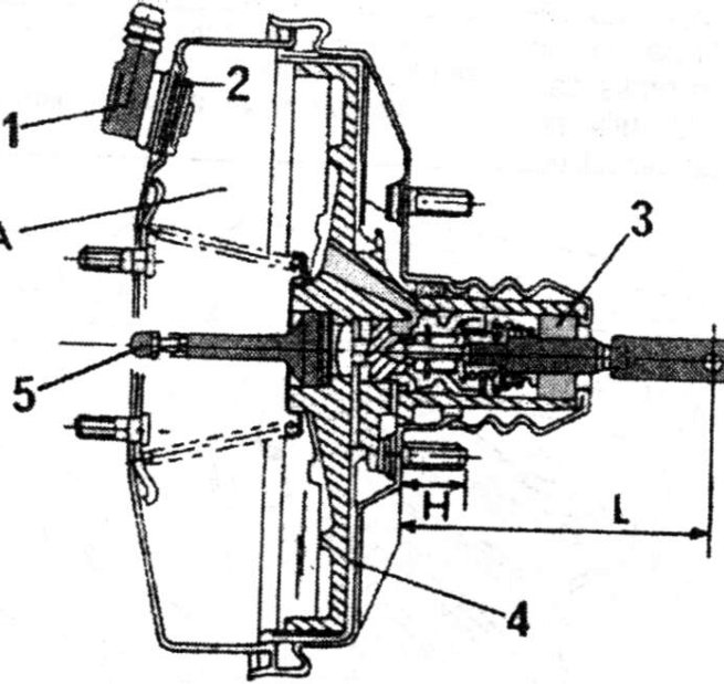
The brake servo unit is not the same for all models. A unit with one chamber or one with a double-chamber (for example in turbo diesel vehicles) are used. The diameter of the brake servo unit has been changed around the beginning of 1992.

- Non-return valve
- Rubber grommet
- Filter
- Diaphragm
- Push rod
A = Working chamber
H = Height of securing studs
L = Length of push rod
Parts & tools for this job For 1987 Peugeot J5
- PARTBrake padsSearch: Peugeot J5 1987 brake pads
- TOOLBrake bleeder kitSearch: one man brake bleeder kit
- FLUIDBrake fluidSearch: brake fluid
Links open Amazon search results in a new tab. As an Amazon Associate I earn from qualifying purchases.