
Sedis Chain Tensioner (page 2 of 2)
- Make
- Peugeot
- Model
- J5 Pocket Mechanic, 1.8 and 2.0 petrol
- Year
- 1987–1994
- Section
- Engine dismantling
EngineSedis Chain Tensioner · page 2 of 2
Note: Big end bearing bearing caps and bearing shells must be kept together if they are to be re-fitted.
- The crankcase will now look as shown in Fig. 1.22. The main bearing caps can be marked in the manner described below. Starting from the flywheel end (cap No. 1), the following paint marks can be seen:
- Cap No. 1 — No marks
- Cap No. 2 — Red
- Cap No. 3 — Green
- Cap No. 4 — White
- Cap No. 5 — Blue
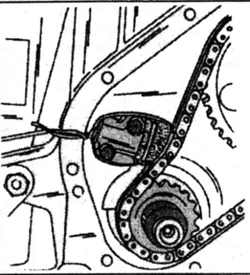
In addition to the paint marks given above, you may also find reference marks in bearing caps 4 and 5 and bearing caps 2 and 3. If no marks are visible, mark each bearing cap either with paint or a centre punch with the respective bearing cap number.
- Unscrew the main bearing cap bolts from the outside towards the inside in several stages until the bolts and bearing caps can be removed. Keep each bearing cap together with its bearing shell.
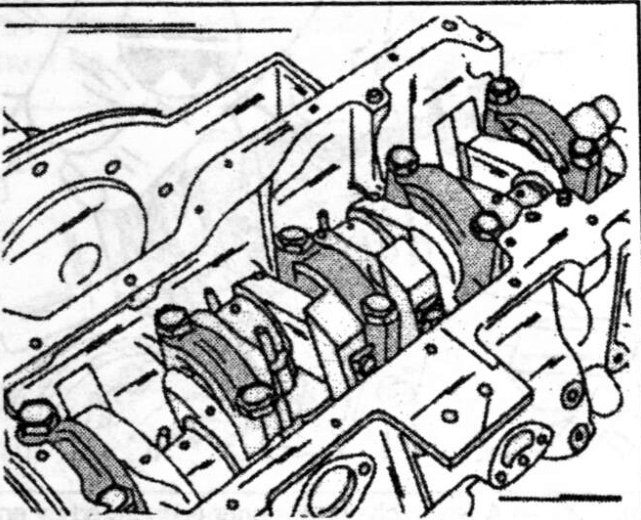
- Carefully lift out the crabnks-haft and remove the remaining bearing shells from the crankcase bores. Mark the bearing shells in accordance with their position in the cylinder block and keep the together with the bearing shell and the bearing cap
- Remove the cylinder liner clamps and withdraw the cylinder liners together with the piston/connection rod assemblies. Mark each cylinder liner with the cylinder number, if they are to be refitted. A sticking cylinder liner will have to be removed with a piece of wood and a hammer. Place the cylinder block on one side to do this. Remove the pistons and con rods out of the cylinder liner bores. Mark the piston crowns with the cylinder number.
- Dismantle the pistons and connecting rods as described later on. We recommend to attach the big end bearing caps and bearing shells to the connecting rods (the correct ones) until you dismantle the assemblies. The pistons and connecting rod assemblies can then be stored as shown in Fig. 1.23 on a clean sheet of paper or cloth.
Parts & tools for this job For 1987 Peugeot J5
- PARTEngine gasket setSearch: Peugeot J5 1987 engine gasket set
- TOOLTorque wrenchSearch: 3/8 inch torque wrench
- TOOLFeeler gauge setSearch: feeler gauge set
Links open Amazon search results in a new tab. As an Amazon Associate I earn from qualifying purchases.