
Selector cable
- Make
- Rover
- Model
- 200 Workshop Manual
- Year
- 1995–1999
- Section
- Repairs › Selector cable
Automatic gearboxSelector cable · page 1 of 2
Refit
- Position kickdown cable in vehicle.
- Secure kickdown outer cable to gearbox housing.
- Using a piece of stiff wire with a hook on the end, connect inner cable to valve cam inside
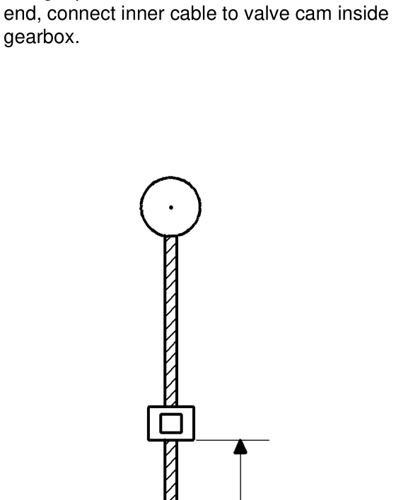
gearbox.
- Holding kickdown cable as straight as possible, fully extent inner cable and secure crimp at distance A. Distance A= 57.0 mm ± 0.5 mm
- Fit kickdown cable to abutment bracket.
- Connect inner cable to throttle cam.
- Fit fluid pan as detailed in Fluid pan gasket. See AUTOMATIC GEARBOX - ’CVT’, Repairs.
- Fit starter motor. See ELECTRICAL, Repairs.
NOTE: The kickdown cable should be routed over the hose between the air cleaner and throttle body.
- Remove stand(s) and lower vehicle.
- Adjust throttle and kickdown cables. See AUTOMATIC GEARBOX - ’CVT’, Adjustments.
SELECTOR CABLE
Service repair no - 44.15.08
Remove
- Remove front console. See BODY, Interior trim components.
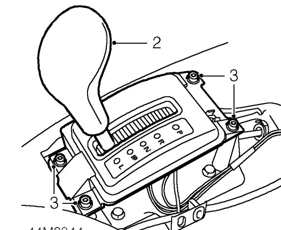
- Position selector lever in ’L’.
- Remove 4 Allen screws securing selector lever nacelle to body and collect washers.
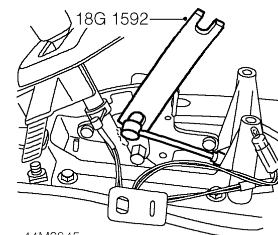
- Using tool 18G 1592 disconnect selector cable ball joint from selector lever.
Parts & tools for this job For 1995 Rover 200
- PARTTransmission filter kitSearch: Rover 200 1995 transmission filter kit
- FLUIDAutomatic transmission fluidSearch: Rover automatic transmission fluid
- TOOLFluid transfer pumpSearch: fluid transfer pump
Links open Amazon search results in a new tab. As an Amazon Associate I earn from qualifying purchases.