
Sunroof relay (page 4 of 4)
- Make
- Rover
- Model
- 400 Body Repair Manual
- Year
- 1995–2000
- Section
- Sunroof
BodySunroof relay · page 4 of 4
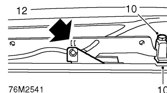
- Position culisse with its adjustable stop directly above slot in slide.
- Check both culisse are correctly timed.
- Adjust stop screws as necessary: Loosen stop screw, align to marks and position stop screw clamp to rear of slot, tighten clamp screw to 3.5 Nm.
NOTE: Stop should just contact plastic pad as it enters slide.
- Fit drain channel and tighten screws to 2.5 Nm.
- Fit sunroof frame assembly. See this section.
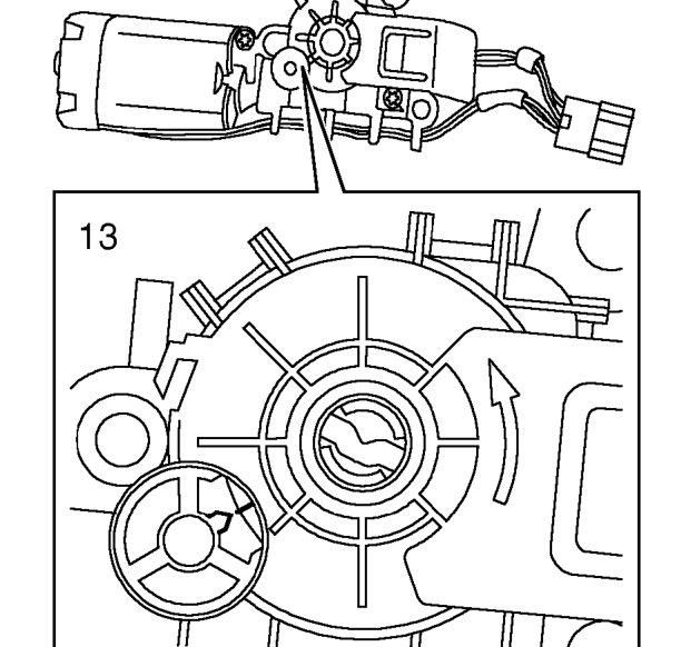
- Check motor is correctly timed. Slot in idle cam aligned with gear. Adjust using key from tool kit or flat bladed screwdriver.
- Carefully position motor and engage drive cables, tighten screws to 4 Nm.
- Fit connector to bracket and connect multiplug.
- Fit sunroof glass. See this section.
- Check operation of sunroof.
- Refit headlining. See this section.
Parts & tools for this job For 1995 Rover 400
- TOOLDigital multimeterSearch: automotive digital multimeter
- PARTAssorted fuse kitSearch: car fuse assortment kit
- TOOLWire crimper and connector kitSearch: wire crimper connector kit
Links open Amazon search results in a new tab. As an Amazon Associate I earn from qualifying purchases.