
Airbag control and diagnostic unit - ’d’ series (page 2 of 2)
- Make
- Rover
- Model
- 400 Body Repair Manual
- Year
- 1995–2000
- Section
- Repairs
‹ Prev Airbag control and diagnostic unit - ’d’ seriesNext › Driver’s airbag control and diagnostic unit - ’k’ ’l’ and ’t’ series
Restraint systemsAirbag control and diagnostic unit - ’d’ series · page 2 of 2
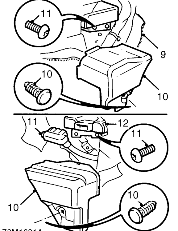
- Pull back carpet for access to control and diagnostic unit protective covers.
- Remove studs securing protective covers and remove covers from unit.
- Disconnect multiplug and remove 4 Torx screws securing control and diagnostic unit.
- Remove unit from LH side.
Refit
CAUTION: Ensure unit faces are clean and free from burrs. An incorrectly mounted unit could cause the system to malfunction.
- Position unit, fit Torx screws and tighten to 9 Nm.
- Connect multiplug.
- Fit protective covers over unit and fit retaining studs.
- Reposition carpet over unit covers.
- Fit foot rest, fit and tighten bolts.
- Remove RED safety connector from passenger airbag module multiplug and secure in storage clip.
- Connect passenger airbag module multiplug to airbag harness.
- Fit glove box. See BODY, Interior trim components.
- Remove RED safety connector from drivers airbag module multiplug and secure in storage clip.
- Connect drivers airbag module multiplug.
- Fit access panel to steering wheel and secure with screw.
- Connect both battery leads, earth lead last.
- Carry out system check by turning the ignition on and checking that the SRS warning light illuminates then extinguishes after 3 seconds.
‹ Prev Airbag control and diagnostic unit - ’d’ seriesNext › Driver’s airbag control and diagnostic unit - ’k’ ’l’ and ’t’ series
Parts & tools for this job For 1995 Rover 400
- TOOLOBD2 scannerSearch: OBD2 scanner
- TOOLDigital multimeterSearch: automotive digital multimeter
- TOOLBack-probe test leadsSearch: back probe test leads
Links open Amazon search results in a new tab. As an Amazon Associate I earn from qualifying purchases.