
Fluid flow circuit (Steering)
- Make
- Rover
- Model
- 400 Workshop Manual
- Year
- 1995–2000
- Section
- Description and operation › Fluid flow circuit
Fluid flow circuit
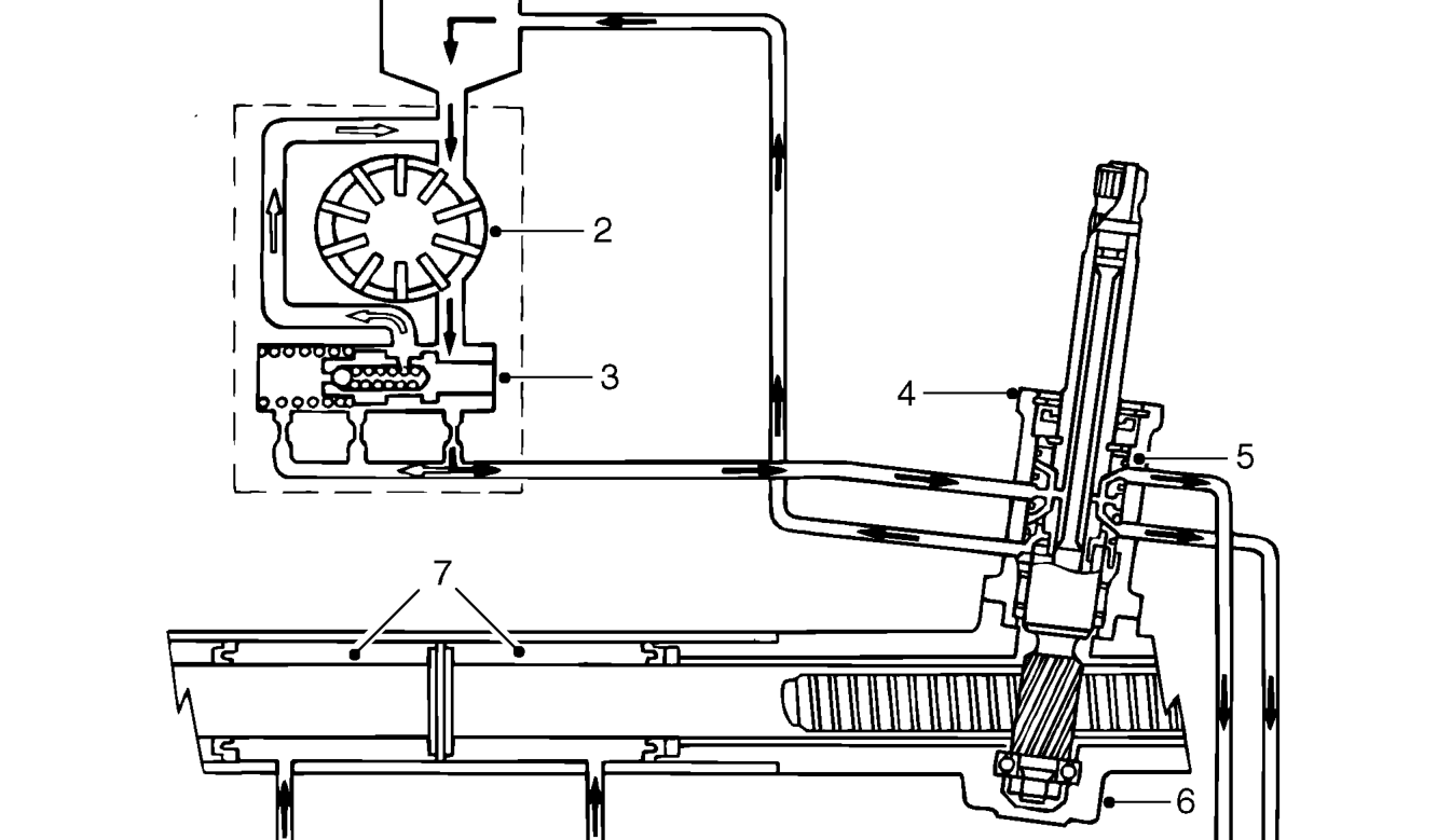
- Reservoir - power steering fluid
- Power steering pump
- Flow control valve and relief valve
- Valve unit
Power assistance is integral with the steering gear. Hydraulic pressure to operate the system is generated by a vane-type pump which is driven by a belt from the crankshaft pulley. The amount of fluid and pressure is regulated by the flow control valve built into the pump. Fluid pressure from the pump is delivered to the valve unit around the steering pinion. The control unit valve controls hydraulic pressure and changes direction of flow. Fluid is directed to the appropriate side of the power cylinder where rack thrust is generated. Fluid returning from the power cylinder, flows through a loop in the return pipe which acts as a fluid cooler before entering the reservoir where the fluid is allowed to settle.
- Spool valve
- Steering gearbox
- Power cylinders
Parts & tools for this job For 1995 Rover 400
- TOOLDigital multimeterSearch: automotive digital multimeter
- PARTAssorted fuse kitSearch: car fuse assortment kit
- TOOLWire crimper and connector kitSearch: wire crimper connector kit
Links open Amazon search results in a new tab. As an Amazon Associate I earn from qualifying purchases.