
Steering (Valve unit): Description and operation
- Make
- Rover
- Model
- 400 Workshop Manual
- Year
- 1995–2000
- Section
- Description and operation › Valve unit
Valve unit
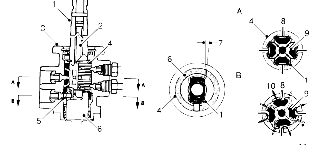
- Input shaft
- Torsion bar
- Valve unit
- Rotary valve
- Pin - pinion shaft groove
- Pinion shaft
- Pinion shaft angular movement
- From pump
- Return passage
- Passage to power cylinder
- Passage from power cylinder
The rotary valve is coaxial with the pinion shaft and controls hydraulic pressure and distribution. The pinion shaft is double with the input shaft connected to the pinion gear by a torsion bar. The pin inserted in the valve and pinion shaft groove is engaged, this allows the pinion shaft and valve to rotate together and deflect under load through a set angle.
When the steering is turned against high steering loads, the reaction force created by the rack against the pinion causes the input shaft to twist the torsion bar within a set angle. This change in alignment of the valve, opens ports to direct fluid to and from the power cylinders.
A- Low assist B- High assist
Parts & tools for this job For 1995 Rover 400
- PARTEngine gasket setSearch: Rover 400 1995 engine gasket set
- TOOLTorque wrenchSearch: 3/8 inch torque wrench
- TOOLFeeler gauge setSearch: feeler gauge set
Links open Amazon search results in a new tab. As an Amazon Associate I earn from qualifying purchases.