Workshop Manuals Factory service & repair Rover
01 Information02 General data03 Engine04 Engine management system – PGM-Fi05 Cooling system, manifold and exhaust06 Clutch07 Manual gearbox08 Automatic gearbox09 Drive shafts10 Differential – manual gearbox11 Differential – automatic gearbox12 Steering13 Suspension14 Brakes and ABS15 Brakes – ABS BY416 Body17 Heating and ventilation18 Electrical19 Supplementary restraint system (SRS)
Rover Rover 600 Repair Manual - Volumes 1 and 2 - 2nd Edition09 · Drive shafts
09 · Transmission

47M0073 (page 2 of 5)

Make
Rover
Model
600 Rover 600 Repair Manual - Volumes 1 and 2 - 2nd Edition
Section
Repairs
Drive shafts47M0073 · page 2 of 5
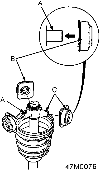
Diagram of a driveshaft spider assembly with callouts A, B, and C indicating the roller and marks on the joint housing.
A Spider B Roller C Marks 13. Fit the rollers to the spider with their high shoulders facing outward. Note: ● Reinstall the rollers in their original positions on the spider by aligning the marks. ● To prevent it falling off, hold the driveshaft so the spider and roller point up.
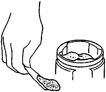
Illustration of a hand using a tool to pack grease into a driveshaft joint component.
47M0077 14. Pack the inboard joint with the joint grease included in the new driveshaft set. Grease Quantity = 120 – 130 g
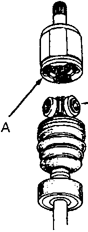
Exploded view of an inboard joint assembly showing the joint and driveshaft connection with callout A.
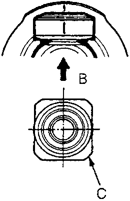
Top-down diagram of the inboard joint holder showing spline direction arrow B and holder position C.
47M0078 A Inboard Joint B Spline direction C Holder 15. Fit the inboard joint onto the driveshaft. CAUTION: ● Reinstall the inboard joint onto the driveshaft by aligning the marks on the inboard joint and the rollers. ● Hold the driveshaft assembly so the inboard joint points up to prevent it falling off. Note: Align the holder direction of the rollers toward the slot of inboard joint as shown.

Parts & tools for this job For Rover 600

Links open Amazon search results in a new tab. As an Amazon Associate I earn from qualifying purchases.