
47M0073 (page 3 of 5)
- Make
- Rover
- Model
- 600 Rover 600 Repair Manual - Volumes 1 and 2 - 2nd Edition
- Section
- Repairs
Drive shafts47M0073 · page 3 of 5
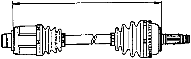
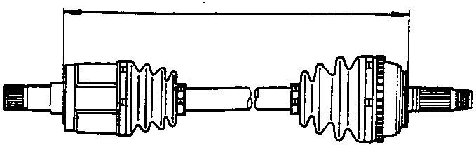
- Adjust the length of drive shafts to figure below, then adjust the boots to halfway between full compression and full extension.
RH shaft = 466 – 471 mm
Automatic LH shaft = 824 – 829 mm
Manual LH shaft = 456 – 461 mm
Note: Ends of boots seat in groove of drive shaft and joint.
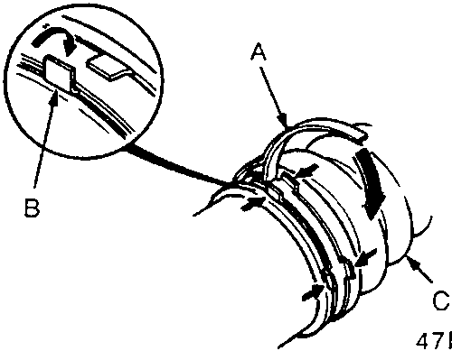
A Boot Band
B Locking Tabs
C Boot
- Install new boot bands on the boots and bend both sets of locking tabs.
- Lightly tap on the doubled – over portions to reduce their height.
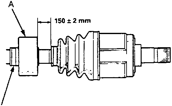
A Dynamic Damper
B Dynamic Damper Band
- Position the dynamic damper as shown.
- Install a new dynamic damper band and bend down both sets of locking tabs.
- Lightly tap on the doubled – over portion of the band to reduce its height.
Parts & tools for this job For Rover 600
- PARTWheel bearingSearch: Rover 600 wheel bearing
- TOOLBearing puller kitSearch: wheel bearing puller kit
- PARTCV boot kitSearch: Rover 600 cv boot kit
Links open Amazon search results in a new tab. As an Amazon Associate I earn from qualifying purchases.