
47M0073 (page 4 of 5)
- Make
- Rover
- Model
- 600 Rover 600 Repair Manual - Volumes 1 and 2 - 2nd Edition
- Section
- Repairs
Drive shafts47M0073 · page 4 of 5
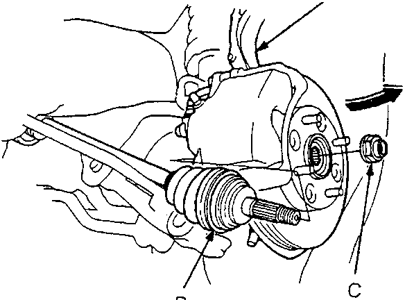
- A Knuckle
- B Outboard Joint
- C Spindle Nut
- Install the outboard joint in the knuckle, then loosely install the new spindle nut.
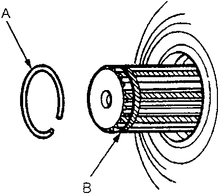
- A Set Ring
- B Set Ring Groove
- Apply 1.0 – 1.5 g of specified grease to the whole spline surface of the intermediate shaft.
Note: After applying grease, remove the grease from the spline grooves at intervals of 2 – 3 splines and from the set ring groove so air can bleed from the inboard joint.
- Install the new set ring onto the driveshaft or intermediate shaft groove.
CAUTION: Always use a new set ring whenever the driveshaft is being installed.
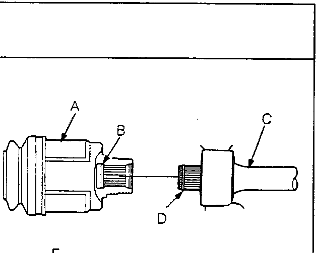
- A Inboard Joint
- B Groove
- C Intermediate Shaft
- D Set Ring
- E Inboard Joint
- F Differential
- Insert the inboard end of the driveshaft into the differential or intermediate shaft until the set ring locks in the groove.
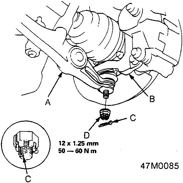
- A Lower Arm
- B Knuckle
- C Cotter Pin
- D Castle Nut
Parts & tools for this job For Rover 600
- PARTWheel bearingSearch: Rover 600 wheel bearing
- TOOLBearing puller kitSearch: wheel bearing puller kit
- PARTCV boot kitSearch: Rover 600 cv boot kit
Links open Amazon search results in a new tab. As an Amazon Associate I earn from qualifying purchases.