
Intermediate Shaft Removal (page 3 of 5)
- Make
- Rover
- Model
- 600 Rover 600 Repair Manual - Volumes 1 and 2 - 2nd Edition
- Section
- Repairs
Drive shaftsIntermediate Shaft Removal · page 3 of 5
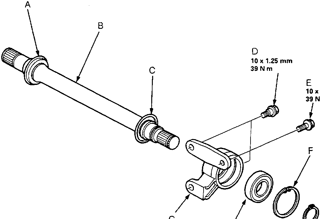
39 N m
2.0 – 3.5 g
- A Intermediate Shaft Ring
- B Intermediate Shaft
- C Bearing Support Ring
- D Dowel Bolts
- E Flange Bolt
- F Internal Circlip
- G Bearing Support
- H Intermediate Shaft Bearing – replace
- I External Circlip
- J Outer Seal – replace
- K Set Ring – replace
Note:
- Clean the disassembled parts with solvent, and dry them thoroughly with compressed air.
- Be careful not to damage the metal rings on the intermediate shaft during reassembly.
- Insert 2.0 – 3.6 g of grease inside outer seal before reassembly.
Parts & tools for this job For Rover 600
- PARTWheel bearingSearch: Rover 600 wheel bearing
- TOOLBearing puller kitSearch: wheel bearing puller kit
- PARTCV boot kitSearch: Rover 600 cv boot kit
Links open Amazon search results in a new tab. As an Amazon Associate I earn from qualifying purchases.