
R134a General precautions (page 2 of 2)
- Make
- Rover
- Model
- 600 Rover 600 Repair Manual - Volumes 1 and 2 - 2nd Edition
- Section
- Information
Heating and ventilationR134a General precautions · page 2 of 2
Note:
- Only use a gauge set for refrigerant R134a.
- use a vacuum pump adapter which equipped with a check valve to prevent the backflow of the vacuum pump oil.
- When an A/C system has been opened to the atmosphere, such as during installation or repair, it must be evacuated using an R134a refrigerant vacuum pump. (if the system has been opened for several days, the receiver/drier should be replaced.)
- Connect a R134a refrigerant gauge, pump and refrigerant containers (cans of R134a) as shown.
Note: do not open the cans.
- Start the pump, then open both pressure valves and evacuation valve (two valve gauge: evacuation stop valve). Run the pump for about 15 minutes. Close both pressure valves and the evacuation valve (two valve gauge: evacuation stop valve) and stop the pump. The low pressure gauge should indicate 700mmHg (27 in – Hg) and remain steady with the valves closed.
Note: If low pressure does not reach more than 700mmHg (27 in – Hg) in 15 minutes, there is probably a leak in the system. Check for leaks, and repair (see Leak Test).
- If there are no leaks, open the valves and continue pumping for at least another 15 minutes. Then close both valves and stop the pump.
THREE VALVE GAUGE
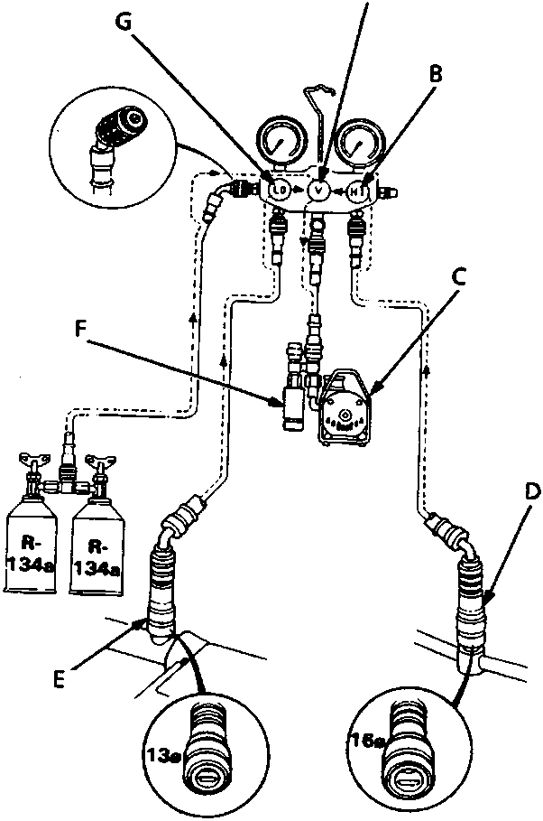
- A Evacuation valve
- B High pressure valve
- C Vacuum pump
- D High pressure quick joint
- E Low pressure quick joint
- F Check valve
- G Low pressure valve
TWO VALVE GAUGE
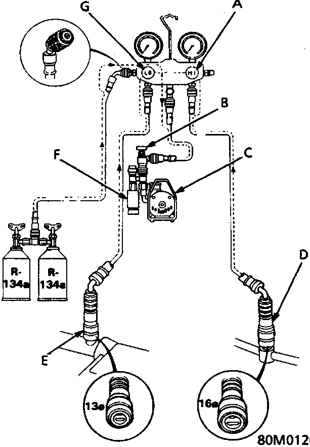
- A High pressure valve
- B Evacuation stop valve
- C Vacuum pump
- D High pressure quick joint
- E Low pressure quick joint
- F Check valve
- G Low pressure valve
Parts & tools for this job For Rover 600
- TOOLA/C manifold gauge setSearch: AC manifold gauge set
- TOOLUV leak detection kitSearch: AC UV leak detection kit
- PARTCabin filterSearch: Rover 600 cabin filter
Links open Amazon search results in a new tab. As an Amazon Associate I earn from qualifying purchases.