
Three valve gauge
- Make
- Rover
- Model
- 600 Rover 600 Repair Manual - Volumes 1 and 2 - 2nd Edition
- Section
- Information › Three valve gauge
Heating and ventilationThree valve gauge
Note:
- Only use a gauge set for refrigerant R134a.
- use a vacuum pump adapter which is equipped with a check valve to prevent the backflow of the vacuum pump oil.
WARNING: When handling refrigerant (R134a) observe all safety precautions, see R134a general precautions.
CAUTION: Do not overcharge the system; the compressor will be damaged.
- After the leak test, check that the high pressure valve is closed and start the engine.
Note: Run the engine below 1500 rpm.
- Open the front door
Turn the A/C switch ON.
Set the temperature control knob to MAX. COOL.
Set the mode control knob to VENT. - Turn the heater fan switch to "V" (MAX)
- Open the low pressure valve and charge with R134a refrigerant.
WARNING:
- Do not open the high pressure valve
- Do not turn the cans upside down.
- Charge the system with refrigerant capacity. Refrigerant capacity: 750 + 0/ − 50g (26 + 0/ − 20 oz).
- When fully charged, close the low pressure valve and refrigerant cans. Check the system.
- Stop the engine and disconnect the charge hose quickly.
- Check the system for leaks using a leak detector suitable for refrigerant R134a.
Note: Check for leaks, particularly around the compressor, condenser and receiver/drier.
THREE VALVE GAUGE
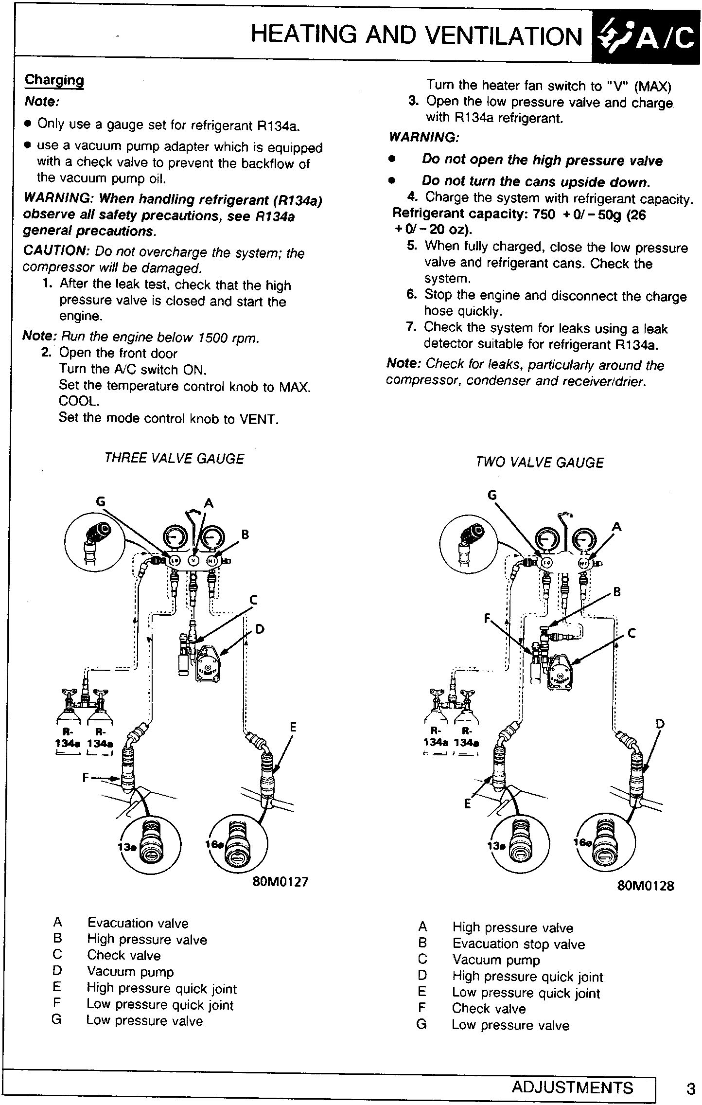
- A Evacuation valve
- B High pressure valve
- C Check valve
- D Vacuum pump
- E High pressure quick joint
- F Low pressure quick joint
- G Low pressure valve
TWO VALVE GAUGE
- A High pressure valve
- B Evacuation stop valve
- C Vacuum pump
- D High pressure quick joint
- E Low pressure quick joint
- F Check valve
- G Low pressure valve
Parts & tools for this job For Rover 600
- PARTEngine gasket setSearch: Rover 600 engine gasket set
- TOOLTorque wrenchSearch: 3/8 inch torque wrench
- TOOLFeeler gauge setSearch: feeler gauge set
Links open Amazon search results in a new tab. As an Amazon Associate I earn from qualifying purchases.