
Information: Special tools (page 2 of 2)
- Make
- Rover
- Model
- 600 Rover 600 Repair Manual - Volumes 1 and 2 - 2nd Edition
- Section
- Information
SteeringSpecial tools · page 2 of 2
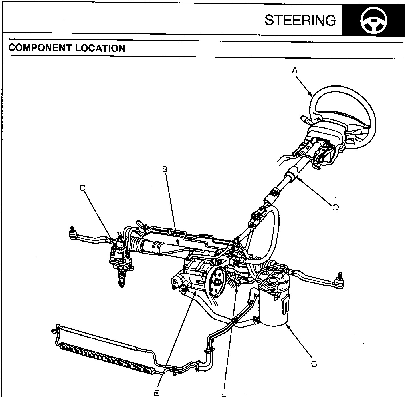
- A Steering Wheel (with SRS)
- B Steering Gearbox
- C Power Steering Speed Sensor
- D Steering Column
- E Power Steering Pump
- F Valve Body Unit
- G Fluid Reservoir
Note:
- If an intact airbag assembly has been removed from a scrapped car or has been found defective or damaged during transit, storage or service, it should be deployed, see ELECTRICAL.
- Before removing the steering gearbox, remove the ignition key to keep the steering shaft from turning.
- After installing the steering gearbox, check the wheel alignment and adjust if necessary, see SUSPENSION.
CAUTION:
- All SRS electrical wiring harnesses are covered with yellow outer insulation.
- Replace the entire affected SRS harness assembly if there is an open circuit or damage to the wiring.
Parts & tools for this job For Rover 600
- TOOLTie rod end toolSearch: tie rod end puller
- TOOLBall joint separatorSearch: ball joint separator
- FLUIDPower steering fluidSearch: Rover power steering fluid
Links open Amazon search results in a new tab. As an Amazon Associate I earn from qualifying purchases.