
Gearbox (page 2 of 7)
- Make
- Rover
- Model
- 600 620 Diesel Repair Manual Supplement
- Year
- 1995–1999
- Section
- Repairs
Manual gearboxGearbox · page 2 of 7
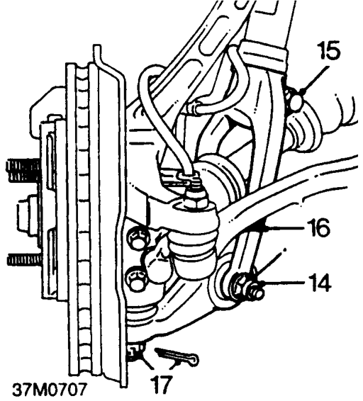
- Remove and discard nut and withdraw damper fork bolt from LH lower arm.
- Remove pinch bolt from damper fork.
- Remove LH damper fork.
- Remove split pin from lower ball joint nut, discard split pin and remove castle nut.
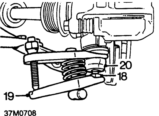
- Screw a 12 mm nut onto ball pin end. If necessary, apply penetrating oil to joint.
- Break taper joint using tool 18G 1707 and separate ball pin from lower arm.
CAUTION: Ensure cross-bar on tool is at right angles (as shown). Be careful not to damage ball joint boot.
- Release LH lower arm ball pin from hub.
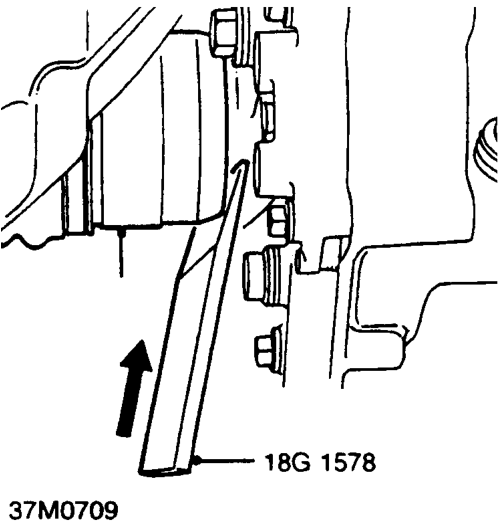
- Insert 18G 1578 between drive shaft housing and gearbox to disengage drive shaft circlip from differential by pulling on the inboard housing.
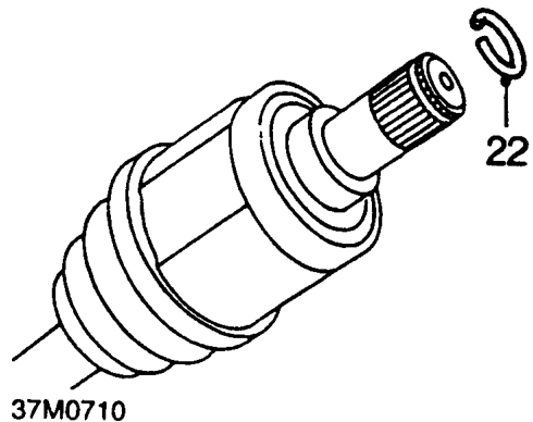
- Remove and discard circlip from LH drive shaft.
- Fit plastic bag over end of drive shaft.
- Repeat above operations and disconnect RH suspension and drive shaft.
Parts & tools for this job For 1995 Rover 600
- PARTClutch kitSearch: Rover 600 1995 clutch kit
- TOOLClutch alignment toolSearch: clutch alignment tool
- FLUIDGear oilSearch: Rover 600 manual gearbox oil
Links open Amazon search results in a new tab. As an Amazon Associate I earn from qualifying purchases.