
Gearbox (page 4 of 7)
- Make
- Rover
- Model
- 600 620 Diesel Repair Manual Supplement
- Year
- 1995–1999
- Section
- Repairs
Manual gearboxGearbox · page 4 of 7
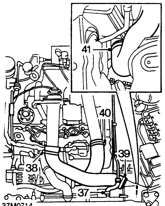
- Slacken clip and disconnect expansion tank return pipe from radiator.
- Slacken clip and disconnect air intake hose from inlet manifold intake pipe.
- Slacken clip and remove air intake hose from intercooler.
- Slacken clip and release turbocharger hose from turbocharger pipe.
- Slacken clip and remove turbocharger hose from intercooler.
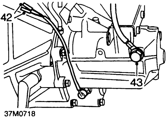
- Disconnect 2 reverse light switch connectors.
- Remove bolt securing earth lead to gearbox.
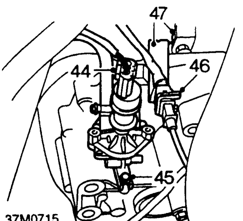
- Disconnect speed sensor multiplug.
- Remove bolt securing power steering speed sensor, release sensor and position aside.
- Release crank sensor multiplug from bracket and disconnect multiplug.
- Remove nut securing crank sensor bracket to gearbox, remove bracket.
- Position trolley jack to support engine.
CAUTION: Use a block of wood or hard rubber pad to protect sump.
- Release fuel filter from mounting bracket and position aside.
Parts & tools for this job For 1995 Rover 600
- PARTClutch kitSearch: Rover 600 1995 clutch kit
- TOOLClutch alignment toolSearch: clutch alignment tool
- FLUIDGear oilSearch: Rover 600 manual gearbox oil
Links open Amazon search results in a new tab. As an Amazon Associate I earn from qualifying purchases.