
4. Fix the problem (Wiring diagrams)
- Make
- Rover
- Model
- 600 620 Diesel Repair Manual Supplement
- Year
- 1995–1999
- Section
- General information › 4. Fix the problem
4. Fix the problem
Once the specific problem is identified make the repair. Be sure to use the proper tools and safe procedures.
5. Intermittent failure
The term Intermittent Failure is used when a system may have had a failure but checks out OK through all your tests. You may need to road test the vehicle to reproduce the failure, or if the problem was a loose connection you may have unknowingly solved it while doing tests.
6. Open or short circuits
An Open is a break in a wire or at a connection. A Short is an accidental connection of a wire to earth, or a positive feed. In simple electronics; this means something won’t work at all. In complex electronics; like Electronic Control Units (ECU’s) this means something works but not the way it is supposed to.
7. Confirm and verify repairs
Always confirm that your diagnosis and repair is complete by verifying the complaint and symptom. Then road test the vehicle when repairs are completed.
Connector types and connector probing
Despite the many different appearances and colours connectors can be grouped into three categories.
1. Connectors with covers
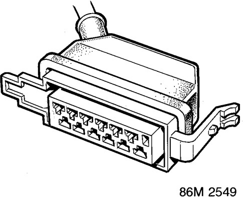
Examples of this connector are on the engine management ECU and the fuel injector connectors.
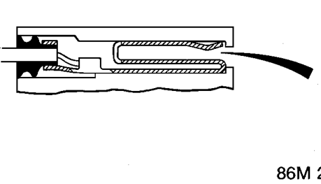
Insert test probe here
For testing at these style of connectors bring the tester probe into contact with the terminal from the connector side of wire harness connectors. For female connectors, insert the special probe carefully.
NOTE: Do not attempt to remove rubber seal and probe into the rear of the connector as damage to the seal will occur.
Parts & tools for this job For 1995 Rover 600
- TOOLDigital multimeterSearch: automotive digital multimeter
- PARTAssorted fuse kitSearch: car fuse assortment kit
- TOOLWire crimper and connector kitSearch: wire crimper connector kit
Links open Amazon search results in a new tab. As an Amazon Associate I earn from qualifying purchases.