
Typical wiring connector faults (Wiring diagrams)
- Make
- Rover
- Model
- 600 620 Diesel Repair Manual Supplement
- Year
- 1995–1999
- Section
- General information › Typical wiring connector faults
Wiring diagramsTypical wiring connector faults
Typical wiring connector faults
Crimped over insulation
Symptom
No continuity between the terminal and wire.
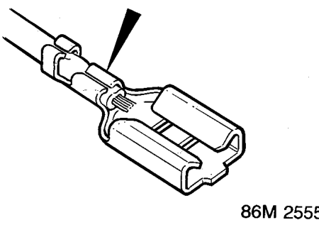
Wire insulation under crimp
Cause
The terminal does not make proper contact with the wire because the crimp is over the insulation.
Action
Replace wiring terminal Be careful not to make the wire too short, if necessary add a length of wire and join using a "Duraseal" heatshrink connector. See Repair Techniques.
Backed out of connector
Symptom
No continuity between terminal and component, intermittent or no contact.
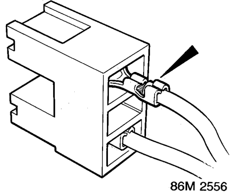
Terminal not properly latched in housing
Cause
Terminal keeper (barb) not properly latched in the housing.
Action
Try pushing the pin in, then pull back lightly to see if the pin comes out. Carefully bend keeper (barb) on terminal to allow secure retention, or replace terminal if damaged.
Parts & tools for this job For 1995 Rover 600
- TOOLDigital multimeterSearch: automotive digital multimeter
- PARTAssorted fuse kitSearch: car fuse assortment kit
- TOOLWire crimper and connector kitSearch: wire crimper connector kit
Links open Amazon search results in a new tab. As an Amazon Associate I earn from qualifying purchases.