
Wiring diagrams (Introduction): General information
- Make
- Rover
- Model
- 600 620 Diesel Repair Manual Supplement
- Year
- 1995–1999
- Section
- General information › Introduction
INTRODUCTION
Wiring Diagrams and connectors.
Wiring between connectors and components shown in the diagrams represents the actual wiring as it exists on the vehicle. Against each wire is a wire colour code to allow for easy identification of each wire (refer to the wire colour chart).
Power Distribution
The Power Distribution diagram shows the connections from the battery to the engine and passenger compartment fuseboxes. It also shows the internal circuitry of both the passenger and engine compartment fuse boxes.
Earth Distribution
The earth distribution diagram shows the individual earth points and all the circuits affected by them.
SYMBOLS USED IN THE CIRCUIT DIAGRAMS
Wire colour
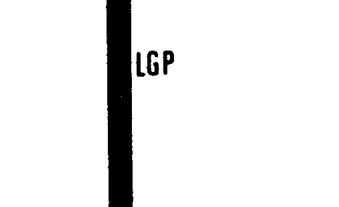
Wire insulation is either all one colour, or is one predominant colour with a stripe in a second colour. Wire colours are identified by a letter code, the main colour is identified first. LG/P = Light green / Purple stripe.
Line types
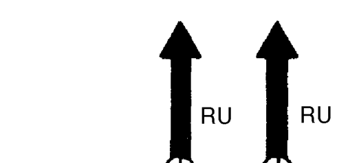
This means the wire connects to another circuit or component.
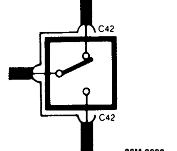
This means that these wires are in connector C42.
Parts & tools for this job For 1995 Rover 600
- TOOLDigital multimeterSearch: automotive digital multimeter
- PARTAssorted fuse kitSearch: car fuse assortment kit
- TOOLWire crimper and connector kitSearch: wire crimper connector kit
Links open Amazon search results in a new tab. As an Amazon Associate I earn from qualifying purchases.