
Wiring diagrams (Components): General information
- Make
- Rover
- Model
- 600 620 Diesel Repair Manual Supplement
- Year
- 1995–1999
- Section
- General information › Components
Wiring diagramsComponents
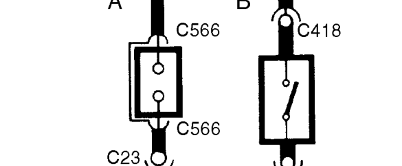
Connector - Direction of the ’symbol’ indicates male and female halves of connector.
A. Plug on lead (Flylead) wired directly to the component.
B. Connector plugs directly into component.
Components

Name or description - appears next to the component.
Earth points
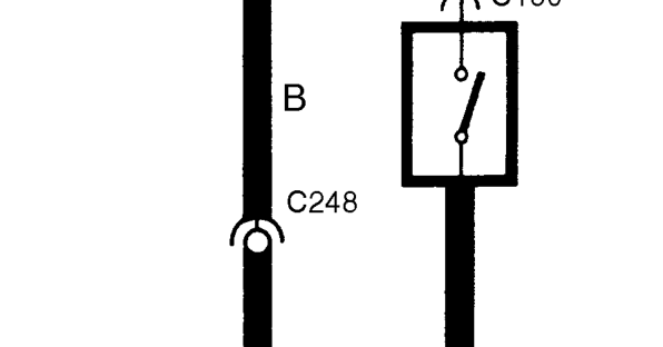
An earth symbol indicates the earth terminal. Each earth wire is numbered.
An earth symbol adjacent to the component - indicates electrical earth is direct through the component mounting.

Identifies Radio Frequency Interference (RFI) shielded wire. The shielding is always connected to earth.
Parts & tools for this job For 1995 Rover 600
- TOOLDigital multimeterSearch: automotive digital multimeter
- PARTAssorted fuse kitSearch: car fuse assortment kit
- TOOLWire crimper and connector kitSearch: wire crimper connector kit
Links open Amazon search results in a new tab. As an Amazon Associate I earn from qualifying purchases.