
Increase pressure phase (Brakes)
- Make
- Rover
- Model
- Coupé, Cabriolet & Tourer 200/400 Coupé, Cabriolet & Tourer Workshop Manual
- Section
- Description and operation › Increase pressure phase
BrakesIncrease pressure phase
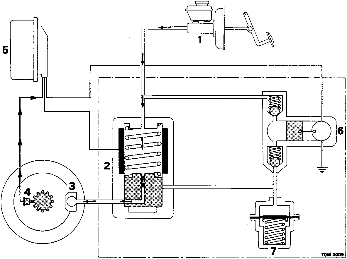
- Master cylinder
- Solenoid valve
- Wheel caliper
- Wheel sensors
- Brake ECU
- Return pump
- Accumulator
Increase pressure phase
Hydraulic modulator
With the vehicle in motion, the ECU receives signals from the four wheel sensors. From these signals the ECU can determine the speed of the vehicle. This is the speed which the ECU uses as a reference when evaluating the deceleration of each wheel.
This reference speed is continually calculated, even during braking. If one or more of the wheels are decelerating faster than the others, indicating a wheel is near the point of locking, the anti - lock sequence will be initiated.
The hydraulic modulator has three operation phases:
- Increase pressure phase: the ABS system is at rest and fluid pressure from the master cylinder is allowed to pass through the solenoid valves in the hydraulic modulator to operate the caliper on each wheel.
- Maintain pressure phase: The caliper is isolated from the master cylinder preventing any pressure increase due to increased pedal pressure.
- Decrease pressure phase: The caliper is connected to the return pump which pumps the fluid back to the master cylinder.
Parts & tools for this job For Rover Coupé, Cabriolet & Tourer
- PARTBrake padsSearch: Rover Coupé, Cabriolet & Tourer brake pads
- TOOLBrake bleeder kitSearch: one man brake bleeder kit
- FLUIDBrake fluidSearch: brake fluid
Links open Amazon search results in a new tab. As an Amazon Associate I earn from qualifying purchases.