
Cooling system components
- Make
- Rover
- Model
- Coupé, Cabriolet & Tourer 200/400 Coupé, Cabriolet & Tourer Workshop Manual
- Section
- Description and operation › Cooling system components
Cooling systemCooling system components
COOLING SYSTEM COMPONENTS
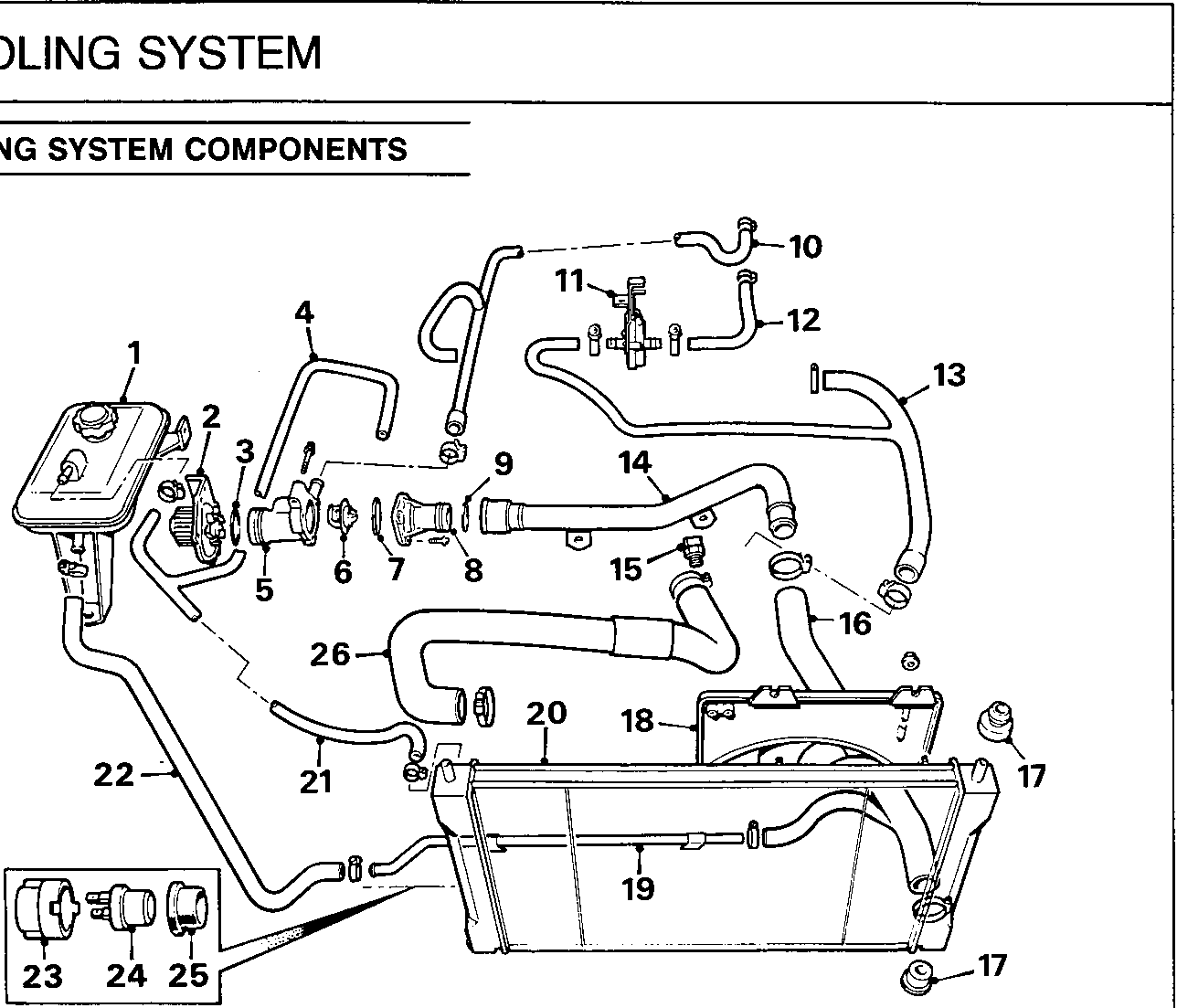
26M 0162
1.4 K8
| 1. Expansion tank | 15. Coolant temperature sensor |
| 2. Coolant pump | 16. Bottom hose |
| 3. Coolant pump 'O' ring seal | 17. Radiator mounting bushes |
| 4. Hose – expansion tank to inlet manifold | 18. Cooling fan and cowl |
| 5. Thermostat housing | 19. Pipe – expansion tank to bottom hose |
| 6. Thermostat | 20. Radiator |
| 7. Sealing ring | 21. Hose – radiator to expansion tank |
| 8. Thermostat cover | 22. Hose – pipe to expansion tank |
| 9. 'O' ring | 23. Locking ring |
| 10. Hose – expansion tank to heater | 24. Thermostatic switch |
| 11. Heater valve | 25. Sealing ring |
| 12. Hose – heater matrix feed | 26. Top hose |
| 13. Hose – heater matrix return | |
| 14. Pipe – bottom hose to thermostat |
Parts & tools for this job For Rover Coupé, Cabriolet & Tourer
- FLUIDCoolantSearch: Rover coolant antifreeze
- PARTThermostatSearch: Rover Coupé, Cabriolet & Tourer thermostat
- TOOLCooling system pressure testerSearch: cooling system pressure tester
Links open Amazon search results in a new tab. As an Amazon Associate I earn from qualifying purchases.