
Rotor-armature
- Make
- Alfa Romeo
- Model
- 147 Factory Service Manual
- Year
- 2000–2002
- Section
- Engine ignition › Rotor-armature
ROTOR-ARMATURE
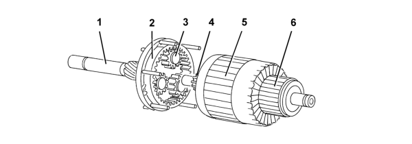
- 1 Shaft
- 2 Ring gear
- 3 Satellite/planet gears
- 4 Pinion/sun gear
- 5 Armature
- 6 Manifold/switch
The diagram below shows the rotor-armature assembly.
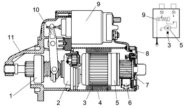
- 1 Pinion with free wheel
- 2 Epicyclic reduction gear
- 3 Rotor permanent mangets
- 4 Complete polar casing
- 5 Armature or rotor
- 6 Blades
- 7 Manifold
- 8 Manifold side support
- 9 Engagment relay
- 10 Lever
- 11 Control side support
Given that the magnetic field is created by permanent magnets, the energizing is the same in all motor operating conditions; in addition, as there are no energizing windings, there is neither an energizing current nor ohmic resistance: the total
resistance depends solely on the armature circuit. The rotation speed is only affected by the current which passes through the blades and reaches the rotor depending on the voltage. Since the motor is equipped with permanent magnets, i.e. with fixed
polarity, the direction of rotation depends on how the current is sent to the blades.
When the rotor rotates it transmits movement to the three satellite gears on special supports which transmit their torque to the ring gear on the output shaft where the pinion which rotates the flywheel can be found. The optimum reduction ratio 1:4.26
is 4.26 revolutions of the rotor for each revolution of the ring gear and the presence of the permanent magnets makes it possible to construct motors of equal power from a simple design which are small in size compared with motors which have windings.
Parts & tools for this job For 2000 Alfa Romeo 147
- PARTBrake padsSearch: Alfa Romeo 147 2000 brake pads
- TOOLCaliper piston rewind toolSearch: brake caliper piston rewind tool
- FLUIDBrake fluidSearch: brake fluid
Links open Amazon search results in a new tab. As an Amazon Associate I earn from qualifying purchases.