
E3046 Boot opening
- Make
- Alfa Romeo
- Model
- 147 Factory Service Manual
- Year
- 2000–2002
- Section
- Electrical activation devices › E3046 Boot opening
E3046 Boot opening
Description
The boot open motor is operated by:
- the button on the dashboard;
- the remote control.
The control unit built into the commands unit on the door controls the operation of the boot lock release: it receives the request to open the boot from the Body Computer or from the control signal from the relevant button on the dashboard., and consequently issues a command to an external relay, located under the dashboard behind the Body Computer.
The boot opening logic is as follows:
- when the ignition is on, the control button causes the boot to open if the vehicle speed is 0 km/h;
- with the ignition off, or when one of the doors is opened, the control button operates for a timed period of 3 minutes.
Whenever the control button is pressed, a confirmation beep is issued - via a signal transmitted on the CAN - by the instrument panel buzzer.
The remote control receiver aerial is connected directly to the Body Computer which contains the electronics of the receiver proper: the remote control is located in the key, on which a specific button controls the boot release (a further two buttons control the door lock and release Wiring diagram E3040 DOOR LOCKING DEVICE ). The Body Computer receives the boot open request from the remote control and, with the ignition off, sends the command to the unit on the door.
Description of operation
The Body Computer M1 receives as input the signals coming from the aerial-receiver P93, which is connected to pins 21 and 31 of connector A.
Via the CAN line, the Body Computer M1 is connected to the controls unit on the door H44.
The controls unit on the door H44 is supplied - pin 24 of connector B - from the line protected by the fuse F39 of the unit under the dashboard B2.
The unit H44 receives as input the signal from the release button, located in the controls unit H12, at pin 3 of connector B.
According to the control logic described above, the unit H44 sends a command from pin 6 of connector A, which energizes the boot opening relay J56 which, supplied by the line protected by fuse F60 of the fuse box B98, controls the operation of the boot lock motor N57.
Wiring diagram
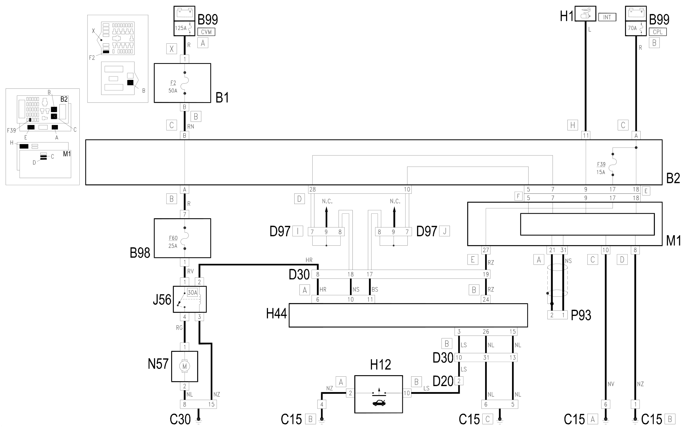
Components
| Code | Component | See |
|---|---|---|
| B01 | Engine compartment junction unit | description 5505A |
| B02 | Junction unit under dashboard | description 5505A |
| B98 | Supplementary fuse box | |
| B99 | Maxifuse box on battery | description 5530B |
| C15 | Facia earth, driver's side | |
| C30 | Left rear earth | |
| D20 | /Rear dashboard coupling | |
| D30 | Rear coupling for /front door. driver's side | |
| D31 | /Front passenger door. rear coupling | |
| D97 | Short circuiting coupling | |
| H01 | Ignition switch | description 5520A |
| H12 | Hazard warning lights, fog lights, rear fog lamps control | description 5505A |
| H44 | Electric windows controls assembly on driver's door | description 7005M |
| J56 | Boot opening relay | |
| M01 | Body computer | description 5505A |
| N57 | Boot lock gearmotor | description 7015B |
| P93 | Receiver aerial for alarm and central locking |
Component location
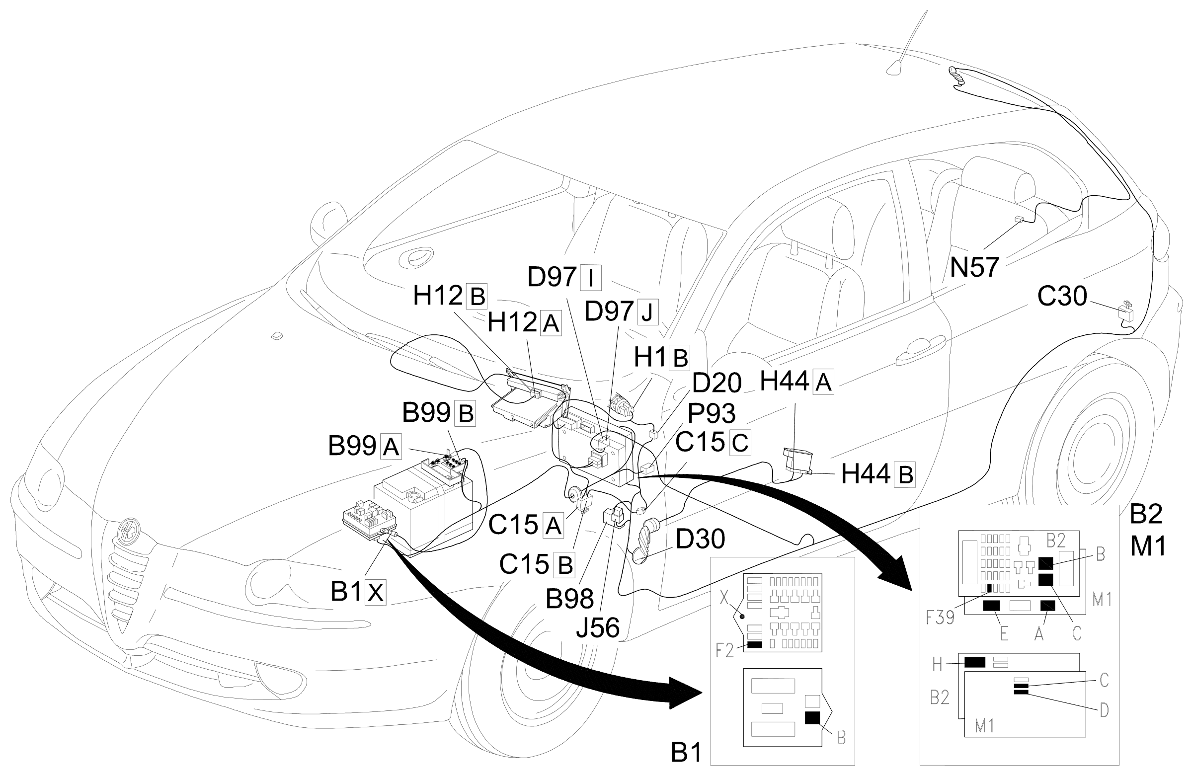
Parts & tools for this job For 2000 Alfa Romeo 147
- TOOLDigital multimeterSearch: automotive digital multimeter
- PARTAssorted fuse kitSearch: car fuse assortment kit
- TOOLWire crimper and connector kitSearch: wire crimper connector kit
Links open Amazon search results in a new tab. As an Amazon Associate I earn from qualifying purchases.