
E3050 Front window mechanism
- Make
- Alfa Romeo
- Model
- 147 Factory Service Manual
- Year
- 2000–2002
- Section
- Electrical activation devices › E3050 Front window mechanism
E3050 Front window mechanism
Description
The control unit built into the controls unit on the door controls the operation of the driver's and passenger's electric window motors.
The driver's and passenger's motors are controlled in both manual and automatic mode, in accordance with the following logic:
For the driver's window:
- if the button is pressed for between 60 and 300 milliseconds, the operation is manual: the window closes/opens only when the button is pressed;
- if the button is pressed for over 300 milliseconds, the operation is instead automatic: even if the relevant button is released, the window continues to close/open as far as the end of travel or until the anti-collision safety system intervenes, if applicable;
- a subsequent press on the button during movement of the window locks it in its current position;
- if the button is pressed for less than 60 milliseconds, it is ignored (it is considered to have been knocked accidentally).
for the passenger's window:
- closing is only manual;
- opening is automatic, the same as for the driver's window
In the case of inconsistent commands issued simultaneously from the driver's and passenger's side, there is no movement.
At each press of the electric windows control buttons, a confirmation beep is emitted by the buzzer in the instrument panel.
The control unit of the controls unit on the door also acquires information on the possible presence of an obstacle during movement of the window during closing via the anti-collision seals: in this case the window travel stops immediately and is reversed; this happens in both manual and automatic operation.
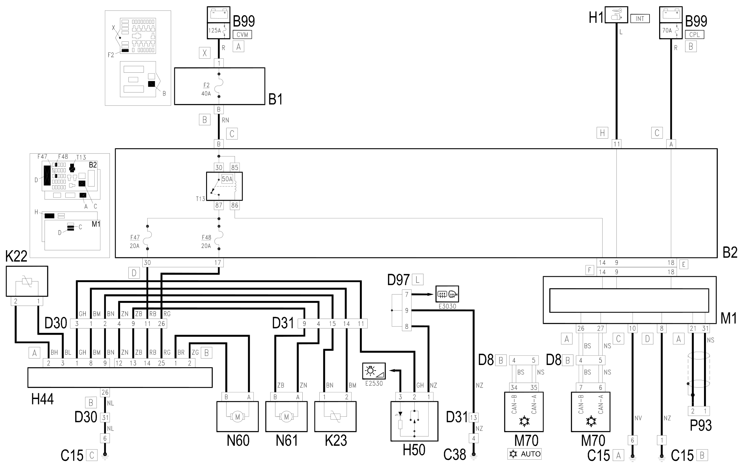
The circuit is controlled by the services relay and protected by two fuses, all located in the unit under the dashboard.
Movement takes place whether the ignition in ON or OFF.
With the ignition on, it takes place as described above; in addition during starting, this relay is temporarily deactivated.
When the ignition is off, the Body Computer keeps the relay activated - which also supplies the door mirrors - for 3 minutes, but deactivates it immediately when one of the two front doors is opened.
Movement is also disabled when the battery voltage is below 10 V.
The windows are automatically closed - with signals which arrive via the CAN network - also when the climate control system is set to recirculation, and the ignition is on (the recirculation state can be activated manually or by the exhaust gas presence sensor Wiring diagram E6020 AIR CONDITIONER .)
The windows are automatically opened or closed by the specific prolonged command (over 4 seconds) sent by the remote control button, if the ignition is off; for more details Wiring diagram E3040 DOOR LOCKING DEVICE .
Description of operation
The services relay T13, located in the unit under the dashboard B2, supplies with the above-mentioned logic and controlled by the Body Computer M1 - pin 14 of connector F - the controls unit on the door H44 - pins 14 and 25 of connector B, via two lines, protected by the fuses F47 and F48.
The unit H44 contains the commands for the driver's and passenger's windows, which supply - pins 1-2 and 13-14 of connector B - the motors N60 (driver's side) and N61 (passenger's side).
Pin 2 of connector A of H44 instead receives the command from the electric window switch on the front door passenger side H50 (this is a simple switch and it does not incorporate any electronics).
Pins 1-8 and 2-3 of connector A of H44 receive the signals from the anti-collision sensors K22 and K23.
Via the CAN line, the node H44 connects to the Body Computer M1 Wiring diagram E1050 CAN CONNECTION LINES and is connected to the climate control unit M70, from which it receives the recirculation signal.
The aerial receiver P93 sends to the Body Computer M1 the open/close signal for the doors and windows, connecting to pins 21 and 31 of connector A.
Wiring diagram
Components
| Code | Component | See |
|---|---|---|
| B01 | Engine compartment junction unit | description 5505A |
| B02 | Junction unit under dashboard | description 5505A |
| B99 | Maxifuse box on battery | description 5530B |
| C10 | Front left earth | |
| C15 | Facia earth, driver's side | |
| C38 | Earth on centre tunnel | |
| D08 | /Air conditioning -heater front coupling | |
| D30 | Rear coupling for /front door. driver's side | |
| D31 | /Front passenger door. rear coupling | |
| D97 | Short circuiting coupling | |
| H01 | Ignition switch | description 5520A |
| H44 | Electric windows controls assembly on driver's door | description 7005M |
| H50 | Electric window switch on .front passenger door | description 7005M |
| K22 | Safety sensor on driver's front door | |
| K23 | Front passenger door safety sensor | |
| M01 | Body computer | description 5505A |
| M70 | Climate control system control unit | description 5040D |
| N60 | Front driver's electric window motor | description 7005M |
| N61 | Front passenger side electric window motor | description 7005M |
| P93 | Receiver aerial for alarm and central locking |
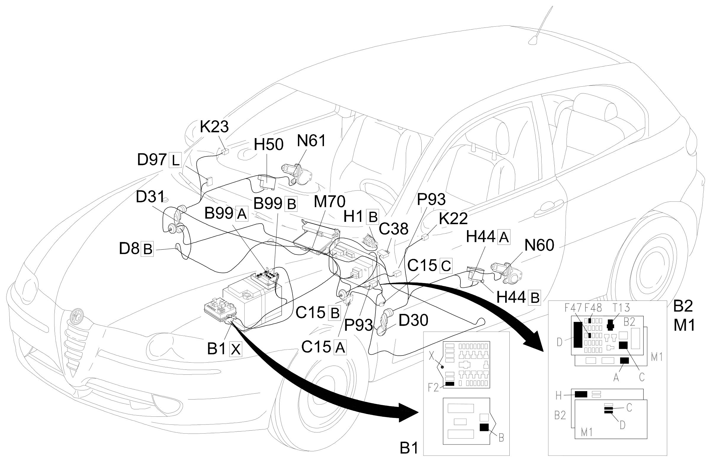
Component location
Parts & tools for this job For 2000 Alfa Romeo 147
- TOOLTrim removal tool kitSearch: trim removal tool kit
- PARTTouch-up paintSearch: Alfa Romeo touch up paint
- PARTPanel clip assortmentSearch: Alfa Romeo panel clips assortment
Links open Amazon search results in a new tab. As an Amazon Associate I earn from qualifying purchases.