
Introduction - engine air supply circuit
- Make
- Fiat
- Model
- Bravo Factory Service Manual
- Year
- 2007–2014
- Section
- Engine air supply circuit › Introduction - engine air supply circuit
INTRODUCTION - ENGINE AIR SUPPLY CIRCUIT
SYSTEM
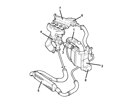
1 - Cold air intake
2 - Air cleaner assembly
3 - Flow meter
4 - Turbocharger
5 - Air/air heat exchanger (intercooler)
6 - Throttle body
7 - Intake chamber
8 - Resonator
DESCRIPTION OF COMPONENTS
THROTTLE BODY - For versions without DPF
Construction specifications
In order to limit the shuddering of the engine whilst it is switching off, a throttle casing has been introduced downstream of the air chamber which has the task of closing the flow of air to the cylinders.
The throttle remains open in all other operating conditions.
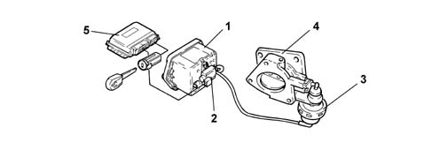
1 - Vacuum reservoir
2 - Solenoid
3 - Throttle casing control actuator
4 - Throttle body
5 - Injection control unit
Operation
When the engine is off, the throttle is open because no vacuum is present.
When the engine is running, the throttle is open because the deactivated solenoid valve closes off the flow of the vacuum to the throttle casing pneumatic actuator.
A vacuum builds up during engine operation.
When the engine is turned off (the key is turned OFF), the injection control unit keeps the actuator supply relay supplied 4 or 5 seconds longer and simultaneously earths the solenoid valve. The valve then opens to send a vacuum to the pneumatic actuator which closes the throttle to cut off the air flow to the cylinders.
CONSTRUCTION SPECIFICATIONS
A pipe leaves the dynamic air intake, located in the top part of the front crossmember, for the air filter.
After having undergone the filtering process, the air is sent to the turbocharger via a main pipe where the pipes coming from the following systems converge:
- shut-off valve system
- crankcase oil vapour recirculation system.
- fuel evaporation control system.
The pressurized air travels from the turbocharger to the intercooler where it undergoes an exchange of heat with the outside and cools and then the compressed air goes via a rigid pipe to the throttle body and from there to the air chamber.
There is a pressure sensor fitted on the rigid pipe between the intercooler and the throttle body and an air intake for the shut-off valve.
The following are fitted on the air chamber:
- motorized throttle body
- intake air pressure/temperature sensor
- fuel manifold with injectors and differential pressure regulator
- fuel evaporation control system valve assembly.
The differential pressure regulator for the fuel supply system is connected to the air chamber via a small rubber pipe.
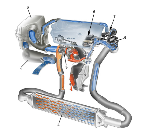
1. Dynamic air intake
2. Air filter
3. Turbocharger
4. Intercooler
5. Air chamber
6. Motorized throttle
7. Shut-off solenoid valve
Parts & tools for this job For 2007 Fiat Bravo
- PARTEngine gasket setSearch: Fiat Bravo 2007 engine gasket set
- TOOLTorque wrenchSearch: 3/8 inch torque wrench
- TOOLFeeler gauge setSearch: feeler gauge set
Links open Amazon search results in a new tab. As an Amazon Associate I earn from qualifying purchases.