
Introduction - fuel tank and components
- Make
- Fiat
- Model
- Bravo Factory Service Manual
- Year
- 2007–2014
- Section
- Fuel tank and pipes › Introduction - fuel tank and components
INTRODUCTION - FUEL TANK AND COMPONENTS
SUBMERGED PUMP ASSEMBLY COMPLETE WITH LEVEL GAUGE
Composition
This essentially consists of:
- an electric fuel pump
- a fuel filter
- a float-type level gauge
- a diaphragm pressure regulator
- a mesh prefilter
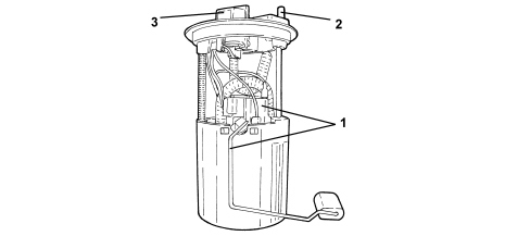
1. Float level sensor
2. Supply connector
3. Electrical connection
Fuel pump
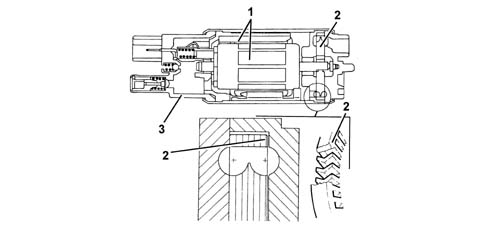
The fuel pump is equipped with a permanent magnet electric motor (1) that controls the pump (2) and a terminal mount cover (3) that contains the electrical and hydraulic connections.
The pump stage is single, peripheral flow type with high performance under low voltage and temperature conditions.
The advantages compared to pumps that operate on volumetric princples are as follows:
- reduced weight
- limited size.
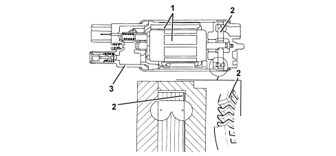
Specifications:
- Capacity = 110 l/h
- Pressure 3.5 bar
- Voltage 12 V
- Current = 7.5 A
Inertia switch
The inertia switch is fitted on the passenger side near the front door pillar. If the vehicle is involved in an impact, it interrupts the connection to earth of the fuel pump and, as a result, the supply of fuel to the injection system.
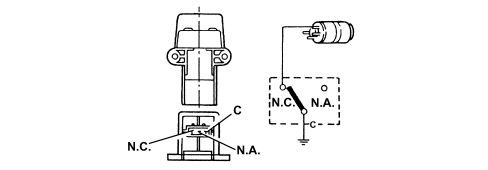
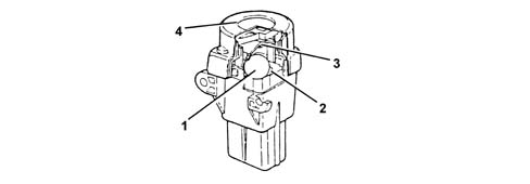
A steel ball (1) fitted in a tapered housing (2) is normally held in place by the attractive force of an adjacent magnet.
Under specific deceleration loads, the ball is released from the magnetic detent and gradually emerges from the tapered mount. Its upward movement is dependent on cone angle.
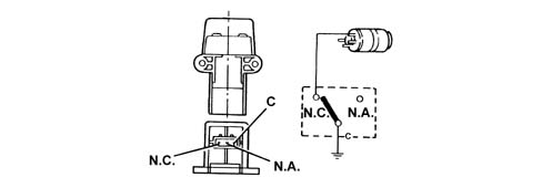
A rapid release mechanism (3) over the ball forms a normally closed (NC) electrical circuit.
When struck by the ball, the mechanism changes position from a NC circuit to a normally open (NA) circuit and breaks the fuel pump earth circuit.
The switch may be reset by pressing a button protected by a flexible cover (4).

If a smell of fuel or fuel system leaks are noted after even an apparently slight impact, do not reset the inertia switch but find and repair the fault to prevent the risk of fire. Otherwise, if no leaks are noted and the vehicle can be driven away, press the button to reactivate the pump.
DESCRIPTION OF COMPONENTS
SUBMERGED PUMP ASSEMBLY COMPLETE WITH LEVEL GAUGE
The fuel pump is part of a single assembly with the level gauge and fuel filter. Components cannot therefore be replaced individually.
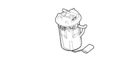
Fuel pump
The fuel pump is equipped with a permanent magnet electric motor (1) that controls the pump (2) and a terminal mount cover (3) that contains the electrical and hydraulic connections.
The pump stage is single, peripheral flow type with high performance under low voltage and temperature conditions.
The advantages compared to pumps that operate on volumetric princples are as follows:
- reduced weight;
- limited size.
INERTIA SWITCH
The inertia switch is fitted on the passenger side near the front door pillar. If the vehicle is involved in an impact, it interrupts the connection to earth of the fuel pump and, as a result, the supply of fuel to the injection system.
A steel ball (1) fitted in a tapered housing (2) is normally held in place by the attraction force of an adjacent magnet.
Under specific acceleration loads, the ball is released from the magnetic detent and gradually emerges from the tapered mount. Its upward movement is dependent on cone angle.
A rapid release mechanism (3) over the ball forms a normally closed (NC) electrical circuit.
When struck by the ball, the mechanism changes position from a NC circuit to a normally open (NA) circuit and breaks the fuel pump earth circuit.
The switch may be reset by pressing a button protected by a flexible cover (4).
If a smell of fuel or fuel system leaks are noted after even an apparently slight impact, do not reset the inertia switch but find and repair the fault to prevent the risk of fire. Otherwise, if no leaks are noted and the vehicle can be driven away, press the button to reactivate the pump.
SUBMERGED PUMP ASSEMBLY COMPLETE WITH LEVEL GAUGE
Composition
This essentially consists of:
- an electric fuel pump
- a fuel filter
- a float-type level gauge
- a maximum pressure regulator
- a mesh pre-filter
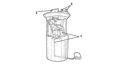
1. Float level sensor
2. Supply and return connectors
3. Electrical connection
Fuel pump
The fuel pump is equipped with a permanent magnet electric motor (1) that controls the pump (2) and a terminal mount cover (3) that contains the electrical and hydraulic connections.
The pump stage is single, peripheral flow type with high performance under low voltage and temperature conditions.
The advantages compared to pumps that operate on volumetric principles are as follows:
- reduced weight
- limited size.
Specifications:
- Capacity = 110 l/h
- Pressure 3.5 bar
- Voltage 12 V
- Current = 7.5 A
Inertia switch
The inertia switch is fitted on the passenger side near the front door pillar. If the vehicle is involved in an impact, it interrupts the connection to earth of the fuel pump and, as a result, the supply of fuel to the injection system.
A steel ball (1) fitted in a tapered housing (2) is normally held in place by the attractive force of an adjacent magnet.
Under specific deceleration loads, the ball is released from the magnetic detent and gradually emerges from the tapered mount. Its upward movement is dependent on cone angle.
A rapid release mechanism (3) over the ball forms a normally closed (NC) electrical circuit.
When struck by the ball, the mechanism changes position from a NC circuit to a normally open (NA) circuit and breaks the fuel pump earth circuit.
The switch may be reset by pressing a button protected by a flexible cover (4).
If a smell of fuel or fuel system leaks are noted after even an apparently slight impact, do not reset the inertia switch but find and repair the fault to prevent the risk of fire. Otherwise, if no leaks are noted and the vehicle can be driven away, press the button to reactivate the pump.
Parts & tools for this job For 2007 Fiat Bravo
- PARTEngine gasket setSearch: Fiat Bravo 2007 engine gasket set
- TOOLTorque wrenchSearch: 3/8 inch torque wrench
- TOOLFeeler gauge setSearch: feeler gauge set
Links open Amazon search results in a new tab. As an Amazon Associate I earn from qualifying purchases.