
Fuel tank - r + r for replacement
- Make
- Fiat
- Model
- Bravo Factory Service Manual
- Year
- 2007–2014
- Section
- Fuel tank and pipes › Fuel tank - r + r for replacement
FUEL TANK - R + R FOR REPLACEMENT
Removing
- Position the vehicle on a lift.
Op. 1076B30 FRONT EXHAUST SILENCER - R + R
Op. 7055B80 UNDERBODY SIDE PROTECTION (ONE) LEFT OR RIGHT - R.R.
Op. 1076A51 HEAT SHIELD FOR EXHAUST PIPE ON FUEL TANK - R.R
Op. 4450B08 RIGHT REAR WHEEL - R.R
Op. 7055B45 RIGHT REAR WHEEL ARCH LINER - R.R
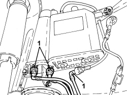
1. Disconnect the rapid connectors for the inlet and outlet pipes from the activated charcoal filter for the fuel vapours.
- Open the clips retaining the pipes previously disconnected to the bodyshell.
Op. 7040A22 INSTRUMENT FACIA COMPLEMENTARY TRIM ELEMENT (ONE) - ARRANGE
Op. 2125C02 GEAR CONTROL LEVER OUTER GAITER R R
Op. 7040L37 GEAR LEVER TRIM - R.R
Op. 7040L73 BOTTLE-HOLDER/ASHTRAY ON REAR TUNNEL TRIM - R.R.
Op. 7040L70 TUNNEL COVER REAR TRIM - R.R.
Op. 7040L20 TUNNEL COVER - R.R
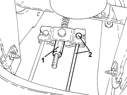
1. Loosen the handbrake lever cable adjustment nut.
2. Disconnect the right rear brake cable from the mounting.
- Fold the rear seat cushions over.
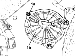
1. Undo the bolts (1a) and remove the access cover to the fuel pump assembly (1b).
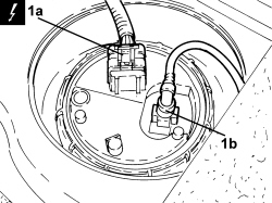
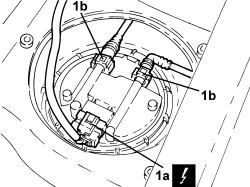
1. Disconnect the electrical connection (1a) and disconnect the rapid connector for the rear fuel supply pipe (1b).
| Description | Connector | |
|---|---|---|
| 1a | Fuel pump and level gauge | See N040 FUEL PUMP AND LEVEL GAUGE |
- Raise the vehicle.
1. Open the handbrake cable retaining clips.
2. Disconnect the right handbrake cable from the bodyshell, open the retaining clips under the reservoir and move it to one side.
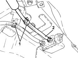
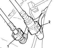
1. Disconnect the fuel vapour pipe rapid connector.
2. Disconnect the intermediate rapid connector for the rear fuel pipe.
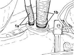
1. Loosen the bands securing the back flow pipe (1a) and fuel filler pipe (1b) and remove them from the tank.
Seal the two openings in the tank appropriately.
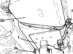
1. Position a hydraulic jack with a suitable support under the fuel tank.
2. Undo the bolts (2a) and remove the fuel tank (2b).
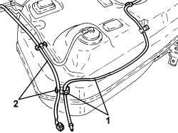
1. Open the retaining clips and remove the rear fuel supply pipe.
2. Open the retaining clips and remove the rear fuel vapour pipe.
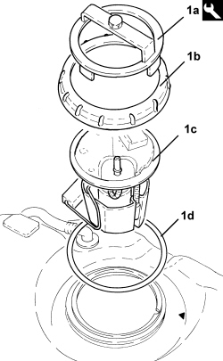
1. Fit the tool (1a), undo the ring nut (1b) securing the submerged pump assembly (1c) from the tank and remove it with the seal (1d).
The seal is replaced every time the ring nut is removed from the tank.
| Tool | Description | Function | Validity |
|---|---|---|---|
| 1870736000 | Spanner | Loosen/tighten ring nut securing fuel pump |
- Release the studs and remove the two tank mounting brackets.
- Proceed with transferring the fuel using suitable equipment.
Refitting
- Fit the two mounting brackets on the tank using new studs.
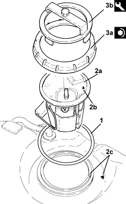
1. Fit a new seal on the tank.
2. Place the submerged pump assembly (2a) back in its housing taking care to ensure that the arrow (2b) on the pump is aligned with the references (2c) on the tank.
3. Tighten the ring nut (3a) securing the pump assembly to the recommended torque using the tool (3b).
| Component | Fastening | dia | Value (daNm) | Validity |
|---|---|---|---|---|
| Fuel pump assembly fastening ring nut | Ring nut | 5.4 ÷ 6.6 |
| Tool | Description | Function | Validity |
|---|---|---|---|
| 1870736000 | Spanner | Loosen/tighten ring nut securing fuel pump |
- Refit the rear fuel vapour pipe and secure it using the retaining clips.
- Refit the rear fuel vapour supply pipe and secure it using the retaining clips.
- Using a suitable hydraulic jack, fit the fuel tank and tighten the bolts to the recommended torque.
| Component | Fastening | dia | Value (daNm) | Validity |
|---|---|---|---|---|
| Fuel tank | Bolt | M8 | 3.2 ÷ 3.9 |
- Remove the hydraulic jack and the support positioned underneath the fuel tank.
- Connect the blow back pipe and to the fuel filler pipe to the tank and tighten the bands.
- Connect the intermediate rapid connector for the rear fuel pipe.
- Connect the fuel vapour pipe rapid connector.
- Place the right handbrake cable in position, connect it to the bodyshell and close the retaining clips.
- Refit the left handbrake cable and close the retaining clip.
- Connect the rapid connectors for the fuel vapour activated charcoal filter inlet and outlet pipes and close the retaining clips on the bodyshell.
- Lower the vehicle.
- Connect the rapid connector for the rear fuel supply pipe, pump side.
- Connect the electrical connection to the fuel pump assembly.
- Place the fuel pump assembly access cover back in its housing and secure it using the bolts.
- Place the rear seat cushions back in their housings.
Op. 3380A04 HANDBRAKE - ADJUST TRAVEL
Op. 7055B45 RIGHT REAR WHEEL ARCH LINER - R.R
Op. 4450B08 RIGHT REAR WHEEL - R.R
Op. 1076A51 HEAT SHIELD FOR EXHAUST PIPE ON FUEL TANK - R.R
Op. 7055B80 UNDERBODY SIDE PROTECTION (ONE) LEFT OR RIGHT - R.R.
Op. 1076B30 FRONT EXHAUST SILENCER - R + R
- Remove the vehicle from the lift.
Op. 7040L20 TUNNEL COVER - R.R
Op. 7040L70 TUNNEL COVER REAR TRIM - R.R.
Op. 7040L73 BOTTLE-HOLDER/ASHTRAY ON REAR TUNNEL TRIM - R.R.
Op. 7040L37 GEAR LEVER TRIM - R.R
Op. 2125C02 GEAR CONTROL LEVER OUTER GAITER R R
Op. 7040A22 INSTRUMENT FACIA COMPLEMENTARY TRIM ELEMENT (ONE) - ARRANGE
Removing
- Position the vehicle on a lift.
Op. 1076B20 REAR EXHAUST SILENCER - R + R
- For versions with DPF:
Op. 1080B81 PARTICULATE FILTER (D.P.F.) - R.R.
- For versions without DPF:
Op. 1080B62 CATALYTIC CONVERTER - R + R
Op. 7055B80 UNDERBODY SIDE PROTECTION (ONE) LEFT OR RIGHT - R.R.
Op. 1076A51 HEAT SHIELD FOR EXHAUST PIPE ON FUEL TANK - R.R
Op. 4450B08 RIGHT REAR WHEEL - R.R
Op. 7055B45 RIGHT REAR WHEEL ARCH LINER - R.R
Op. 7040A22 INSTRUMENT FACIA COMPLEMENTARY TRIM ELEMENT (ONE) - ARRANGE
Op. 2125C02 GEAR CONTROL LEVER OUTER GAITER R R
Op. 7040L37 GEAR LEVER TRIM - R.R
Op. 7040L73 BOTTLE-HOLDER/ASHTRAY ON REAR TUNNEL TRIM - R.R.
Op. 7040L70 TUNNEL COVER REAR TRIM - R.R.
Op. 7040L20 TUNNEL COVER - R.R
1. Loosen the handbrake lever cable adjustment nut.
2. Disconnect the right rear brake cable from the mounting.
- Fold the rear seat cushions over.
1. Undo the bolts (1a) and remove the access cover to the fuel pump assembly (1b).
1. Disconnect the electrical connection (1a) and disconnect the rapid connectors for the fuel supply and return pipes (1b).
| Description | Connector | |
|---|---|---|
| 1a | Fuel pump and level gauge | See N040 FUEL PUMP AND LEVEL GAUGE |
- Raise the vehicle.
1. Open the handbrake cable retaining clips.
2. Disconnect the right handbrake cable from the bodyshell, open the retaining clips under the reservoir and move it to one side.
1. Disconnect the intermediate rapid connectors for the fuel supply and return pipes.
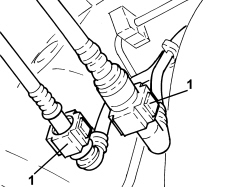
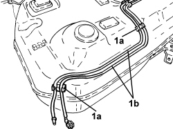
1. Loosen the bands securing the back flow pipe (1a) and fuel filler pipe (1b) and remove them from the tank.
Seal the two openings in the tank appropriately.
1. Position a hydraulic jack with a suitable support under the fuel tank.
2. Undo the bolts (2a) and remove the fuel tank (2b).
1. Open the retaining clips (1a) and remove the rear fuel supply and return pipes (1b).
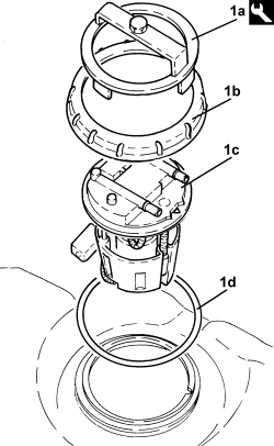
1. Fit the tool (1a), undo the ring nut (1b) securing the submerged pump assembly (1c) from the tank and remove it with the seal (1d).
| Tool | Description | Function | Validity |
|---|---|---|---|
| 1870736000 | Spanner | Loosen/tighten ring nut securing fuel pump |
The seal is replaced every time the ring nut is removed from the tank.
- Release the studs and remove the two tank mounting brackets.
- Proceed with transferring the fuel using suitable equipment.
Refitting
- Fit the two mounting brackets on the tank using new studs.
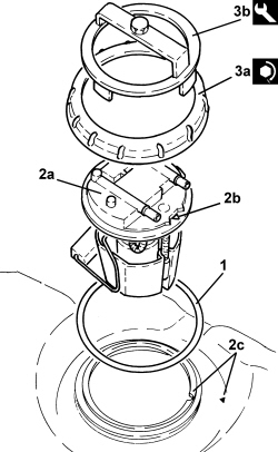
1. Fit a new seal on the tank.
2. Place the submerged pump assembly (2a) back in its housing taking care to ensure that the arrow (2b) on the pump is aligned with the references (2c) on the tank.
3. Tighten the ring nut (3a) securing the pump assembly to the recommended torque using the tool (3b).
| Component | Fastening | dia | Value (daNm) | Validity |
|---|---|---|---|---|
| Fuel pump assembly fastening ring nut | Ring nut | 5.4 ÷ 6.6 |
| Tool | Description | Function | Validity |
|---|---|---|---|
| 1870736000 | Spanner | Loosen/tighten ring nut securing fuel pump |
- Place the rear fuel supply and return pipes in their housings and secure them using the retaining clips.
- Using a suitable hydraulic jack, fit the fuel tank and tighten the bolts to the recommended torque.
| Component | Fastening | dia | Value (daNm) | Validity |
|---|---|---|---|---|
| Fuel tank | Bolt | M8 | 3.2 ÷ 3.9 |
- Remove the hydraulic jack and the support positioned underneath the fuel tank.
- Connect the blow back pipe and to the fuel filler pipe to the tank and tighten the bands.
- Connect the rapid connectors for the rear fuel pipes.
- Place the right handbrake cable in position, connect it to the bodyshell and close the retaining clips.
- Refit the left handbrake cable and close the retaining clip.
- Lower the vehicle.
- Connect the rapid connectors for the rear fuel supply and return pipes, pump side.
- Connect the electrical connection to the fuel pump assembly.
- Place the fuel pump assembly access cover back in its housing and secure it using the bolts.
- Place the rear seat cushions back in their housings.
Op. 3380A04 HANDBRAKE - ADJUST TRAVEL
Op. 7055B45 RIGHT REAR WHEEL ARCH LINER - R.R
Op. 4450B08 RIGHT REAR WHEEL - R.R
Op. 1076A51 HEAT SHIELD FOR EXHAUST PIPE ON FUEL TANK - R.R
Op. 7055B80 UNDERBODY SIDE PROTECTION (ONE) LEFT OR RIGHT - R.R.
- For versions with DPF:
Op. 1080B81 PARTICULATE FILTER (D.P.F.) - R.R.
- For versions without DPF:
Op. 1080B62 CATALYTIC CONVERTER - R + R
Op. 1076B20 REAR EXHAUST SILENCER - R + R
- Remove the vehicle from the lift.
Op. 7040L20 TUNNEL COVER - R.R
Op. 7040L70 TUNNEL COVER REAR TRIM - R.R.
Op. 7040L73 BOTTLE-HOLDER/ASHTRAY ON REAR TUNNEL TRIM - R.R.
Op. 7040L37 GEAR LEVER TRIM - R.R
Op. 2125C02 GEAR CONTROL LEVER OUTER GAITER R R
Op. 7040A22 INSTRUMENT FACIA COMPLEMENTARY TRIM ELEMENT (ONE) - ARRANGE
Removing
- Position the vehicle on a lift.
Op. 1076B30 FRONT EXHAUST SILENCER - R + R
Op. 7055B80 UNDERBODY SIDE PROTECTION (ONE) LEFT OR RIGHT - R.R.
Op. 1076A51 HEAT SHIELD FOR EXHAUST PIPE ON FUEL TANK - R.R
Op. 4450B08 RIGHT REAR WHEEL - R.R
Op. 7055B45 RIGHT REAR WHEEL ARCH LINER - R.R
1. Disconnect the rapid connectors for the inlet and outlet pipes from the activated charcoal filter for the fuel vapours.
- Open the clips retaining the pipes previously disconnected to the bodyshell.
Op. 7040A22 INSTRUMENT FACIA COMPLEMENTARY TRIM ELEMENT (ONE) - ARRANGE
Op. 2125C02 GEAR CONTROL LEVER OUTER GAITER R R
Op. 7040L37 GEAR LEVER TRIM - R.R
Op. 7040L73 BOTTLE-HOLDER/ASHTRAY ON REAR TUNNEL TRIM - R.R.
Op. 7040L70 TUNNEL COVER REAR TRIM - R.R.
Op. 7040L20 TUNNEL COVER - R.R
1. Loosen the handbrake lever cable adjustment nut.
2. Disconnect the right rear brake cable from the mounting.
- Fold the rear seat cushions over.
1. Undo the bolts (1a) and remove the access cover to the fuel pump assembly (1b).
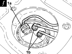
1. Disconnect the electrical connection (1a) and the rapid connectors (1b) for the fuel supply and return pipes.
| Description | Connector | |
|---|---|---|
| 1a | Fuel pump and level gauge | See N040 FUEL PUMP AND LEVEL GAUGE |
Mark the position of the fuel pipes in relation to the connectors on the pump.
- Raise the vehicle.
1. Open the handbrake cable retaining clips.
2. Disconnect the right handbrake cable from the bodyshell, open the retaining clips under the reservoir and move it to one side.
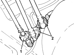
1. Disconnect the fuel vapour pipe rapid connector.
2. Disconnect the fuel vapour pipe rapid connectors.
1. Loosen the bands securing the back flow pipe (1a) and fuel filler pipe (1b) and remove them from the tank.
Seal the two openings in the tank appropriately.
1. Position a hydraulic jack with a suitable support under the fuel tank.
2. Undo the bolts (2a) and remove the fuel tank (2b).
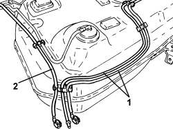
1. Open the retaining clips and remove the fuel supply and return pipes.
2. Open the retaining clips and remove the rear fuel vapour pipe.
1. Fit the tool (1a), undo the ring nut (1b) securing the submerged pump assembly (1c) from the tank and remove it with the seal (1d).
The seal is replaced every time the ring nut is removed from the tank.
| Tool | Description | Function | Validity |
|---|---|---|---|
| 1870736000 | Spanner | Loosen/tighten ring nut securing fuel pump |
- Release the studs and remove the two tank mounting brackets.
- Proceed with transferring the fuel using suitable equipment.
Refitting
- Fit the two mounting brackets on the tank using new studs.
1. Fit a new seal on the tank.
2. Place the submerged pump assembly (2a) back in its housing taking care to ensure that the arrow (2b) on the pump is aligned with the references (2c) on the tank.
3. Tighten the ring nut (3a) securing the pump assembly to the recommended torque using the tool (3b).
| Component | Fastening | dia | Value (daNm) | Validity |
|---|---|---|---|---|
| Fuel pump assembly fastening ring nut | Ring nut | 5.4 ÷ 6.6 |
| Tool | Description | Function | Validity |
|---|---|---|---|
| 1870736000 | Spanner | Loosen/tighten ring nut securing fuel pump |
- Refit the rear fuel vapour pipe and secure it using the retaining clips.
- Place the fuel supply and return pipes in their housings and secure them using the retaining clips.
- Using a suitable hydraulic jack, fit the fuel tank and tighten the bolts to the recommended torque.
| Component | Fastening | dia | Value (daNm) | Validity |
|---|---|---|---|---|
| Fuel tank | Bolt | M8 | 3.2 ÷ 3.9 |
- Remove the hydraulic jack and the support positioned underneath the fuel tank.
- Connect the blow back pipe and to the fuel filler pipe to the tank and tighten the bands.
- Connect the fuel vapour pipe rapid connectors.
- Connect the fuel vapour pipe rapid connector.
- Place the right handbrake cable in position, connect it to the bodyshell and close the retaining clips.
- Refit the left handbrake cable and close the retaining clip.
- Connect the rapid connectors for the fuel vapour activated charcoal filter inlet and outlet pipes and close the retaining clips on the bodyshell.
- Lower the vehicle.
- Connect the rapid connectors for the fuel supply and return pipes, pump side.
- Connect the electrical connection to the fuel pump assembly.
- Place the fuel pump assembly access cover back in its housing and secure it using the bolts.
- Place the rear seat cushions back in their housings.
Op. 3380A04 HANDBRAKE - ADJUST TRAVEL
Op. 7055B45 RIGHT REAR WHEEL ARCH LINER - R.R
Op. 4450B08 RIGHT REAR WHEEL - R.R
Op. 1076A51 HEAT SHIELD FOR EXHAUST PIPE ON FUEL TANK - R.R
Op. 7055B80 UNDERBODY SIDE PROTECTION (ONE) LEFT OR RIGHT - R.R.
Op. 1076B30 FRONT EXHAUST SILENCER - R + R
- Remove the vehicle from the lift.
Op. 7040L20 TUNNEL COVER - R.R
Op. 7040L70 TUNNEL COVER REAR TRIM - R.R.
Op. 7040L73 BOTTLE-HOLDER/ASHTRAY ON REAR TUNNEL TRIM - R.R.
Op. 7040L37 GEAR LEVER TRIM - R.R
Op. 2125C02 GEAR CONTROL LEVER OUTER GAITER R R
Op. 7040A22 INSTRUMENT FACIA COMPLEMENTARY TRIM ELEMENT (ONE) - ARRANGE
Parts & tools for this job For 2007 Fiat Bravo
- PARTEngine gasket setSearch: Fiat Bravo 2007 engine gasket set
- TOOLTorque wrenchSearch: 3/8 inch torque wrench
- TOOLFeeler gauge setSearch: feeler gauge set
Links open Amazon search results in a new tab. As an Amazon Associate I earn from qualifying purchases.