
Introduction - intake and exhaust manifolds
- Make
- Fiat
- Model
- Bravo Factory Service Manual
- Year
- 2007–2014
- Section
- Inlet and exhaust manifolds › Introduction - intake and exhaust manifolds
INTRODUCTION - INTAKE AND EXHAUST MANIFOLDS
AIR CHAMBER
The air chamber is made from plastic and directs the air straight to the cylinder head.
The throttle body, the fuel vapour cut out valve and the intake air pressure/temperature sensor are fitted on the chamber.
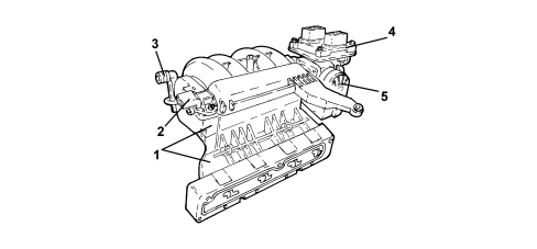
1. Air chamber
2. Air pressure/temperature sensor
3. Fuel vapour pipe connector
4. Injection control unit
5. Throttle body
EXHAUST MANIFOLD
The exhaust manifold is part of the unit that includes the catalytic converter and the first section of the exhaust.
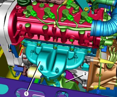
1. Exhaust manifold
2. Catalytic converter
AIR CHAMBER
The continuous adjustment swirl valves are incorporated in the air chamber inside the four additional intake ducts.
The swirl valves are activated by means of an electronically controlled actuator, operated by a PWM type signal that is processed by the electronics with the consequent control of the position. The actuator moves an adjustment shaft which operates on the swirl valves via an idler.
Thanks to the geometric shape of the four additional intake ducts and the swirl valves the fresh gases create a vortex and are directed in the best possible way to the combustion chamber. The filling of the cylinders is therefore excellent.
The continuous adjustment of the swirl valves makes it possible to produce optimum turbulence for all engine speed and load conditions.
Operating specifications:
- temperature interval: between -40°C and +140°C
- input signal: PWM frequency 140Hz
- diagnostic signal: PWM variable frequency from 10 to 100Hz
- power supply voltage: 14V.
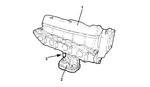
1. Air chamber
2. Swirl throttle control actuator
3. Adjustment shaft
It is possible to adapt the turbulence of the fresh gases inside the combustion chambers to the respective engine load conditions by adjusting the swirl valves.
High turbulence is created in the combustion chamber by closing the swirl valves, thereby allowing an optimum fuel mixture to be injected at low engine revs.
Thanks to this optimum mixture of fuel with fresh gases the emission of pollutant substances is greatly reduced.
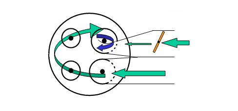
At a higher number of engine revs the swirl valves are completely open. This produces a reduction in the turbulence of the fresh gases and increases the degree of filling.
A higher degree of cylinder filling produces an increase in engine power.
AIR CHAMBER
The air capacity chamber is made from aluminium. It receives pressurised air cooled by the intercooler and carries it directly to the cylinder head.
There is a motorized throttle body fitted on versions with a DPF at the air chamber inlet or a pneumatically controlled one for versions without a DPF.
Intake manifold
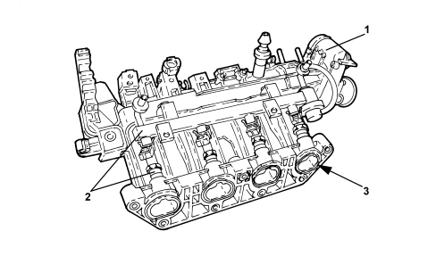
The intake manifold and air chamber are made from plastic with good mechanical resistance properties and support the throttle bottle (1) and the fuel distribution manifold - injectors assembly (2).
There is a special gasket (3) on each inlet duct for connection with the cylinder head.
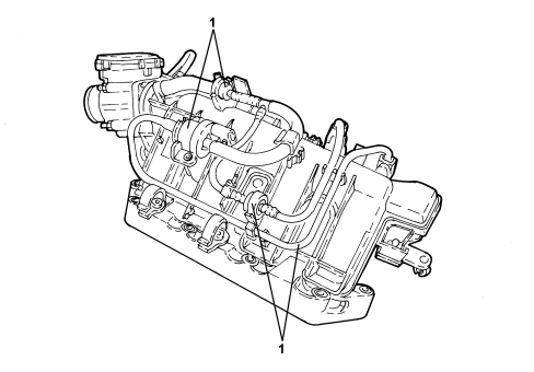
The valve assembly (1) for managing the fuel vapours is fitted at the rear of the air chamber.
Exhaust manifold
The exhaust manifold features the division of the ducts in a 4-2-1 formation.
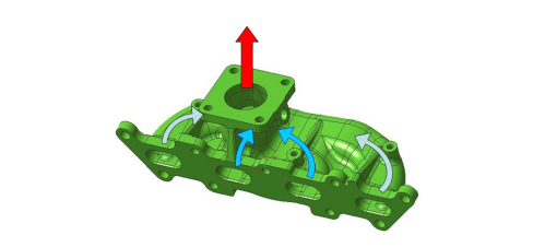
As can be seen in the diagram, the ducts for the 1st and 4th cylinders join the ones for the 2nd and 3rd cylinders on the flange connected to the turbocharger so that they are separated from one another.
This solution allows the flow of exhaust gases not to create an obstruction thereby improving performance and reducing consumption and pollutant emissions.
Parts & tools for this job For 2007 Fiat Bravo
- PARTExhaust gasketSearch: Fiat Bravo 2007 exhaust gasket
- TOOLPenetrating oilSearch: penetrating oil
- TOOLOBD2 scannerSearch: OBD2 scanner
Links open Amazon search results in a new tab. As an Amazon Associate I earn from qualifying purchases.