
Air chamber - r.r.
- Make
- Fiat
- Model
- Bravo Factory Service Manual
- Year
- 2007–2014
- Section
- Inlet and exhaust manifolds › Air chamber - r.r.
AIR CHAMBER - R.R.
Removing
Op. 1048A32 HOSE FROM AIR FILTER TO INTAKE MANIFOLD - R + R
Op. 1048A10 AIR FILTER ASSEMBLY - R.R.
Op. 1056B14 THROTTLE CASE - R + R
Op. 1056B60 SINGLE FUEL MANIFOLD PIPE, WITH INJECTORS - R.R.
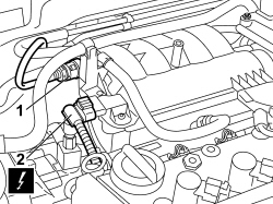
1. Disconnect the intermediate rapid connector for the fuel vapour pipe.
2. Disconnect the electrical connection for the air temperature/pressure sensor.
| Description | Connector | |
|---|---|---|
| 2 | Air pressure - temperature sensor | See K044 AIR TEMPERATURE/PRESSURE SENSOR |
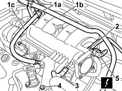
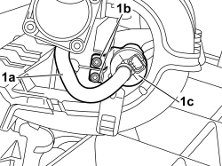
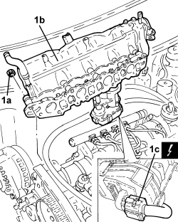
1. Open the bands (1a) and move aside the degassing pipe (1b) and the fuel pipe (1c).
2. Loosen the band and disconnect the brake servo vacuum pipe from the air intake chamber.
3. Disconnect the oil vapour pipe from the air capacity chamber.
4. Undo the bolt securing the air chamber to the cylinder head extension.
5. Disconnect the electrical connection for the fuel vapour solenoid valve.
| Description | Connector | |
|---|---|---|
| 5 | Fuel vapour recovery solenoid valve | See L010 FUEL VAPOUR RECOVERY SOLENOID VALVE |
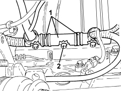
1. Open the retaining clips and move the engine wiring duct aside.
2. Undo the lower bolts securing the air chamber to the cylinder head.
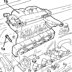
1. Undo the upper bolts (1a) and remove the air chamber assembly (1b).
1. Disconnect fuel vapour pipe (1a) from the air chamber, unscrew the bolts (1b) and remove the fuel vapour solenoid (1c).
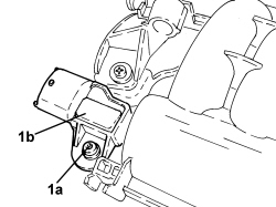
1. Undo the bolt (1a) and remove the air pressure and temperature sensor (1b) complete with O-ring.
Refitting
- Place the air pressure and temperature sensor back in its housing complete with new O-ring and secure it to the chamber using the bolt.
- Place the fuel vapour solenoid valve assembly in position and secure it to the chamber using the bolts.
- Connect the fuel vapour pipe to the chamber and secure it using the clips.
- Place the air chamber assembly in position and tighten the bolts securing it to the cylinder head to the recommended torque.
| Component | Fastening | dia | Value (daNm) | Validity |
|---|---|---|---|---|
| Air chamber - cylinder head side | Bolt (to be replaced) | M7 | 1.3 ÷ 1.6 | 1.4 16v |
- Refit the engine wiring duct and secure it using the clips.
- Refit the fuel pipe and the degassing pipe in their seats and secure with clips.
- Connect the electrical connection for the fuel vapour solenoid valve.
- Tighten the bolt securing the intake chamber to the camshaft housing to the recommended torque.
| Component | Fastening | dia | Value (daNm) | Validity |
|---|---|---|---|---|
| Air chamber - camshaft housing side | Bolt (to be replaced) | M6 | 0.8 ÷ 1.1 | 1.4 16v |
- Connect the brake servo vacuum pipe to the intake chamber and secure it using the band.
- Connect the oil vapour pipe to the air capacity chamber.
- Connect the electrical connection for the air pressure/temperature sensor.
- Connect the intermediate rapid connector for the fuel vapour pipe to the air chamber.
Op. 1056B60 SINGLE FUEL MANIFOLD PIPE, WITH INJECTORS - R.R.
Op. 1056B14 THROTTLE CASE - R + R
Op. 1048A10 AIR FILTER ASSEMBLY - R.R.
Op. 1048A32 HOSE FROM AIR FILTER TO INTAKE MANIFOLD - R + R
Removing
- Position the vehicle on a lift.
Op. 4450B04 RIGHT FRONT WHEEL - R.R
Op. 1016A10 SOUND-PROOFING COVER - R.R
Op. 7055B54 UNDER ENGINE PROTECTION/GUARD - R.R.
Op. 7055B66 ENGINE COMPARTMENT DUST COVER IN RIGHT FRONT WHEEL ARCH - R.R.
Op. 1092G10 SINGLE ENGINE BELT - R.R
Op. 1092A10 CRANKSHAFT PULLEY - R + R
Op. 1092G14 ENGINE COMPONENT SINGLE BELT MOVING TENSIONER - R + R
Op. 1092G20 ENGINE COMPONENT SINGLE BELT FIXED TENSIONER - R + R
Op. 1032D12 TIMING SYSTEM PROTECTIVE COVER(S) - R + R
Op. 1032B10 TOOTHED TIMING BELT - R + R FOR TIMING ADJUSTMENT OR REPLACEMENT
Op. 1060E30 PRESSURE PUMP DRIVE PULLEY - R.R.
Op. 1060F50 FUEL RETURN MANIFOLD - R.R.
Op. 1080C24 E.G.R. SYSTEM SOLENOID - R + R
Op. 1080D34 ENGINE OIL VAPOUR SEPARATOR - R + R
Op. 1060E10 DIESEL INJECTION PRESSURE PUMP - R.R.
Op. 1044B10 FUEL FILTER ASSEMBLY - R + R OR REPLACE
Op. 1008B10 POWER UNIT FRONT SUPPORT FLEXIBLE MOUNTING (TIMING SIDE) - REPLACE
Op. 1060E40 PRESSURE PUMP SUPPORT - R.R.
1. Undo the bolts and disconnect the air supply pipe from the throttle body.
2. Undo the bolts and remove the bracket.
- Disconnect the vacuum pipe from the pneumatic valve on the throttle casing.
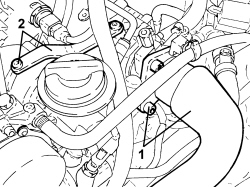
1. Undo the bolts fixing the rigid degassing pipe and move it to one side.
2. Detach the pressure relief sensor electrical connection.
| Description | Connector | |
|---|---|---|
| 2 | Air pressure - temperature sensor | See K044 AIR TEMPERATURE/PRESSURE SENSOR |
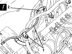
1. Undo the nuts (1a), remove the air chamber (1b) and disconnect the electrical connection from the swirl actuator (1c).
- Remove the gasket.
| Description | Connector | |
|---|---|---|
| 1c | Flow modifier solenoid valve | See L064 FLOW MODIFYING SOLENOID VALVE |
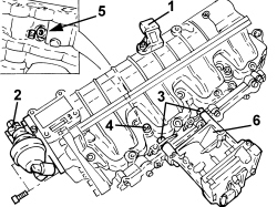
1. Undo the bolt and remove the excess pressure sensor.
2. Undo the bolts and remove the throttle casing.
3. Undo the rear bolts fixing the swirl actuator to the intake manifold.
4. Undo the bolts fixing the chamber to the intake manifold.
5. Undo the upper bolt fixing the swirl actuator to the intake manifold.
6. Remove the swirl actuator.
Refitting
- Place the swirl actuator in position and tighten the bolts to the recommended torque.
| Component | Fastening | dia | Value (daNm) | Validity |
|---|---|---|---|---|
| Swirl actuator | Bolt | M6 | 0.8 ÷ 1.0 | 1.9 JTD 16v |
- Tighten the bolt fixing the chamber to the intake manifold.
- Refit the throttle body in its seat and tighten the bolts to the recommended torque.
| Component | Fastening | dia | Value (daNm) | Validity |
|---|---|---|---|---|
| Throttle body | Bolt | M8 | 2.3 ÷ 2.8 | 1.9 JTD 16v |
- Position the excess pressure sensor in its housing and tighten the bolt.
- Secure the electrical connection for the swirl actuator.
- Place the air chamber, complete with new gasket, back in its housing and tighten the nuts to the recommended torque.
| Component | Fastening | dia | Value (daNm) | Validity |
|---|---|---|---|---|
| Air chamber | Nut | M8 | 2.3 ÷ 2.8 | 1.9 JTD |
- Secure the electrical connection for the pressure relief sensor.
- Fit the rigid degassing pipe in its housing and tighten the bolts.
- Connect the vacuum pipe for the pneumatic valve on the throttle casing.
- Fit the bracket in its housing and secure it using the bolts.
- Connect the air supply pipe to the throttle body and tighten the bolts.
Op. 1060E40 PRESSURE PUMP SUPPORT - R.R.
Op. 1008B10 POWER UNIT FRONT SUPPORT FLEXIBLE MOUNTING (TIMING SIDE) - REPLACE
Op. 1044B10 FUEL FILTER ASSEMBLY - R + R OR REPLACE
Op. 1060E10 DIESEL INJECTION PRESSURE PUMP - R.R.
Op. 1080D34 ENGINE OIL VAPOUR SEPARATOR - R + R
Op. 1080C24 E.G.R. SYSTEM SOLENOID - R + R
Op. 1060F50 FUEL RETURN MANIFOLD - R.R.
Op. 1060E30 PRESSURE PUMP DRIVE PULLEY - R.R.
Op. 1032B10 TOOTHED TIMING BELT - R + R FOR TIMING ADJUSTMENT OR REPLACEMENT
Op. 1032D12 TIMING SYSTEM PROTECTIVE COVER(S) - R + R
Op. 1092G20 ENGINE COMPONENT SINGLE BELT FIXED TENSIONER - R + R
Op. 1092G14 ENGINE COMPONENT SINGLE BELT MOVING TENSIONER - R + R
Op. 1092A10 CRANKSHAFT PULLEY - R + R
Op. 1092G10 SINGLE ENGINE BELT - R.R
Op. 7055B66 ENGINE COMPARTMENT DUST COVER IN RIGHT FRONT WHEEL ARCH - R.R.
Op. 7055B54 UNDER ENGINE PROTECTION/GUARD - R.R.
Op. 1016A10 SOUND-PROOFING COVER - R.R
Op. 4450B04 RIGHT FRONT WHEEL - R.R
- Remove the vehicle from the lift.
Removing
Op. 4450B04 RIGHT FRONT WHEEL - R.R
Op. 7055B66 ENGINE COMPARTMENT DUST COVER IN RIGHT FRONT WHEEL ARCH - R.R.
Op. 7055B54 UNDER ENGINE PROTECTION/GUARD - R.R.
Op. 1092G10 SINGLE ENGINE BELT - R.R
Op. 1016A10 SOUND-PROOFING COVER - R.R
Op. 1092A10 CRANKSHAFT PULLEY - R + R
Op. 1032D26 TIMING SYSTEM FRONT PROTECTIVE COVER (UPPER PART) - R.R.
Op. 1032D27 TIMING SYSTEM FRONT PROTECTIVE COVER (LOWER PART) - R.R.
Op. 1032B10 TOOTHED TIMING BELT - R + R FOR TIMING ADJUSTMENT OR REPLACEMENT
Op. 1060E30 PRESSURE PUMP DRIVE PULLEY - R.R.
Op. 1060F50 FUEL RETURN MANIFOLD - R.R.
Op. 1060E10 DIESEL INJECTION PRESSURE PUMP - R.R.
Op. 1044B10 FUEL FILTER ASSEMBLY - R + R OR REPLACE
Op. 1008B10 POWER UNIT FRONT SUPPORT FLEXIBLE MOUNTING (TIMING SIDE) - REPLACE
Op. 1060E40 PRESSURE PUMP SUPPORT - R.R.
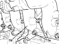
1. Undo the nuts (1a) and remove the air chamber (1b).
- Remove the gasket.
Refitting
- Place the air chamber, complete with new gasket, back in its housing and tighten the nuts to the recommended torque.
| Component | Fastening | dia | Value (daNm) | Validity |
|---|---|---|---|---|
| Air chamber | Nut | M8 | 2.3 ÷ 2.8 | 1.9 JTD |
Op. 1060E40 PRESSURE PUMP SUPPORT - R.R.
Op. 1008B10 POWER UNIT FRONT SUPPORT FLEXIBLE MOUNTING (TIMING SIDE) - REPLACE
Op. 1044B10 FUEL FILTER ASSEMBLY - R + R OR REPLACE
Op. 1060E10 DIESEL INJECTION PRESSURE PUMP - R.R.
Op. 1060F50 FUEL RETURN MANIFOLD - R.R.
Op. 1060E30 PRESSURE PUMP DRIVE PULLEY - R.R.
Op. 1032B10 TOOTHED TIMING BELT - R + R FOR TIMING ADJUSTMENT OR REPLACEMENT
Op. 1032D27 TIMING SYSTEM FRONT PROTECTIVE COVER (LOWER PART) - R.R.
Op. 1032D26 TIMING SYSTEM FRONT PROTECTIVE COVER (UPPER PART) - R.R.
Op. 1092A10 CRANKSHAFT PULLEY - R + R
Op. 1016A10 SOUND-PROOFING COVER - R.R
Op. 1092G10 SINGLE ENGINE BELT - R.R
Op. 7055B54 UNDER ENGINE PROTECTION/GUARD - R.R.
Op. 7055B66 ENGINE COMPARTMENT DUST COVER IN RIGHT FRONT WHEEL ARCH - R.R.
Op. 4450B04 RIGHT FRONT WHEEL - R.R
Removing
- Position the vehicle on a lift.
- Open the fuse box cover in the engine compartment, remove fuse F21 (15A) and start the engine several times until the fuel pressure in the distribution manifold is expended.
- Fit the fuse removed previously and close the fuse box cover.
Op. 7055B54 UNDER ENGINE PROTECTION/GUARD - R.R.
Op. 0010T20 ENGINE COOLANT - CHANGE
Op. 1016A10 SOUND-PROOFING COVER - R.R
Op. 1056B65 SOUND INSULATING COVER FOR INJECTOR ASSEMBLY - R.R.
Op. 1088D48 PIPE FROM ENGINE COOLANT RESERVOIR TO TURBOCHARGER - R.R.
Op. 1048B25 INTERMEDIATE RIGID PIPE BETWEEN HEAT EXCHANGER AND THROTTLE BODY - R R
Op. 1048B30 AIR SUPPLY HOSE FROM RIGID PIPE TO THROTTLE BODY - REPLACE
1. Detach the electrical connection for the throttle body.
| Description | Connector | |
|---|---|---|
| 1 | Integrated throttle body actuator | See N075 BUILT-IN THROTTLE BODY ACTUATOR |
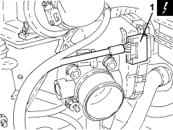
1. Disconnect the electrical connection for the fuel vapour solenoid valve.
| Description | Connector | |
|---|---|---|
| 1 | Fuel vapour recovery solenoid valve | See L010 FUEL VAPOUR RECOVERY SOLENOID VALVE |
2. Open the engine wiring retaining clips.
3. Undo the lower bolts securing the air chamber.
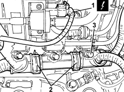
1. Undo the fastenings and remove the air capacity chamber reinforcement.
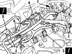
2. Disconnect the rapid connectors, open the retaining clips and move the fuel supply and return pipes to one side.
3. Detach the electrical connections for the injectors.
| Description | Connector | |
|---|---|---|
| 3 | Injector | See N070 INJECTOR |
4. Disconnect the injector wiring coupling and remove it.
5. Disconnect the electrical connection for the air temperature/pressure sensor.
| Description | Connector | |
|---|---|---|
| 5 | Air pressure - temperature sensor | See K044 AIR TEMPERATURE/PRESSURE SENSOR |
6. Disconnect the quick couplings for the fuel vapour delivery and return pipes.
7. Loosen the band and disconnect the brake servor vacuum pipe.
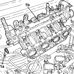
1. Undo the upper bolts (1a) and remove the air chamber (1b).
- Remove the gaskets.
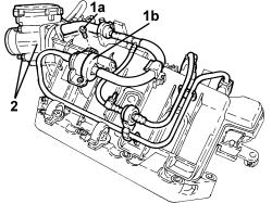
1. Undo the bolts (1a), open the retaining clips and remove the fuel vapour solenoid valve (1b) complete with pipes and one-way valves.
2. Undo the bolts and remove the throttle casing.
- Remove the O-ring from the intake chamber.
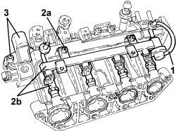
1. Disconnect the vacuum pipe from the fuel pressure regulator.
2. Undo the bolts (2a) and remove the common rail (2b) with injectors (2c).
3. Undo the bolt and remove the air pressure and temperature sensor.
Refitting
- Position the air pressure and temperature sensor in its housing and secure it using the bolt.
- Place the single fuel manifold pipe complete with injectors in its housing and secure it using the bolts.
- Connect the vacuum pipe to the fuel pressure regulator.
- Fit a new O-ring on the intake chamber, throttle body side.
- Place the throttle body back in its housing and tighten the bolts.
- Place the fuel vapour solenoid valve complete with pipes and one-way valves back in its housing, close the retaining clips and tighten the bolts.
- Place the air chamber, complete with new gaskets, back in its housing and tighten the upper bolts to the recommended torque.
| Component | Fastening | dia | Value (daNm) | Validity |
|---|---|---|---|---|
| Air chamber | Bolt (to be replaced) | M7 | 1.3 ÷ 1.6 | 1.4 16v TJet |
- Connect the brake servo vacuum pipe and tighten the band.
- Connect the quick couplings for the fuel vapour delivery and return pipes.
- Connect the electrical connection for the air pressure/temperature sensor.
- Refit the injector wiring in its seat and connect the intermediate coupling.
- Secure the electrical connections for the injectors.
- Place the fuel supply and return pipes in position and connect the rapid connectors.
- Place the air chamber reinforcement back in its housing and tighten the fastenings.
- Close the fuel supply and return pipe retaining clips.
- Tighten the lower bolts fixing the air chamber to the recommended torque.
| Component | Fastening | dia | Value (daNm) | Validity |
|---|---|---|---|---|
| Air chamber | Bolt (to be replaced) | M7 | 1.3 ÷ 1.6 | 1.4 16v TJet |
- Close the engine wiring retaining clips.
- Connect the electrical connection for the fuel vapour solenoid valve.
- Connect the electrical connection for the throttle body.
Op. 1048B30 AIR SUPPLY HOSE FROM RIGID PIPE TO THROTTLE BODY - REPLACE
Op. 1048B25 INTERMEDIATE RIGID PIPE BETWEEN HEAT EXCHANGER AND THROTTLE BODY - R R
Op. 1088D48 PIPE FROM ENGINE COOLANT RESERVOIR TO TURBOCHARGER - R.R.
Op. 1056B65 SOUND INSULATING COVER FOR INJECTOR ASSEMBLY - R.R.
Op. 1016A10 SOUND-PROOFING COVER - R.R
Parts & tools for this job For 2007 Fiat Bravo
- PARTExhaust gasketSearch: Fiat Bravo 2007 exhaust gasket
- TOOLPenetrating oilSearch: penetrating oil
- TOOLOBD2 scannerSearch: OBD2 scanner
Links open Amazon search results in a new tab. As an Amazon Associate I earn from qualifying purchases.