
Engine oil vapour separator - r + r
- Make
- Fiat
- Model
- Bravo Factory Service Manual
- Year
- 2007–2014
- Section
- Emission control system › Engine oil vapour separator - r + r
ENGINE OIL VAPOUR SEPARATOR - R + R
Removing
Op. 1016A10 SOUND-PROOFING COVER - R.R
Op. 1080C24 E.G.R. SYSTEM SOLENOID - R + R
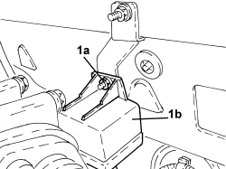
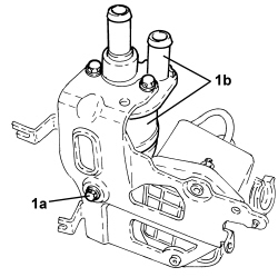
1. Undo the nut (1a) and move the heater plugs control unit (1b) to one side.
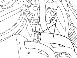
1. Loosen the band and disconnect the oil recovery pipe, separator side.
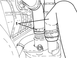
1. Loosen the bands and disconnect the oil vapour intake pipes, separator side.
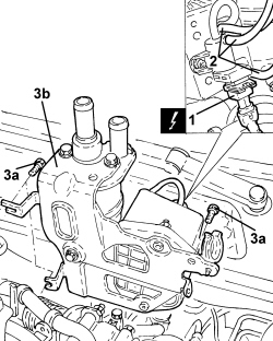
1. Disconnect the electrical connection for the throttle casing solenoid valve.
| Description | Connector | |
|---|---|---|
| Throttle body solenoid valve | See L062 THROTTLE BODY SOLENOID VALVE |
2. Disconnect the vacuum pipes from the vacuum reservoir.
Mark the position of the pipes before removing them.
3. Undo the bolts (3a) and remove the bracket complete with separator and vacuum reservoir (3b).
1. Undo the bolts (1a) and remove the engine oil vapour separator (1b) from the bracket.
Refitting
- Fit the engine oil vapour separator in place and secure it to the bracket using the bolts.
- Position the bracket complete with separator and vacuum reservoir in its housing and tighten the bolts to the recommended torque.
| Component | Fastening | dia | Value (daNm) | Validity |
|---|---|---|---|---|
| Oil vapour separator bracket - intake chamber side | Bolt | M6 | 0.8 ÷ 1.0 | 1.9 JTD 16v |
| Component | Fastening | dia | Value (daNm) | Validity |
|---|---|---|---|---|
| Oil vapour separator bracket - injection pump mounting side | Bolt | M8 | 2.3 ÷ 2.8 | 1.9 JTD 16v |
- Connect the vacuum pipes to the vacuum reservoir.
- Connect the electrical connection for the throttle casing solenoid valve.
- Connect the oil vapour intake pipes, separaator side and tighten the bands.
- Connect the oil recovery pipe, separator side and tighten the band.
- Place the heater plugs control unit in position and secure it using the nut.
Op. 1080C24 E.G.R. SYSTEM SOLENOID - R + R
Op. 1016A10 SOUND-PROOFING COVER - R.R
Removing
Op. 1016A10 SOUND-PROOFING COVER - R.R
Op. 1072B53 AIR CHAMBER REINFORCEMENT BRACKET - R.R.
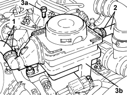
1. Loosen the band and disconnect the oil vapour input pipe to the turbocharger intake, oil vapour separator side.
2. Loosen the band and disconnect the oil vapour input pipe to the air chamber, oil vapour separator side.
3. Undo the bolts (3a) and remove the oil vapour separator (3b).
Refitting
- Refit the oil vapour separator and tighten the bolts.
- Connect the oil vapour input pipe to the air chamber, oil vapour separator side and tighten the bands.
- Connect the oil vapour input pipe to the turbocharger intake, oil vapour separator side and tighten the bands.
Parts & tools for this job For 2007 Fiat Bravo
- PARTEngine gasket setSearch: Fiat Bravo 2007 engine gasket set
- TOOLTorque wrenchSearch: 3/8 inch torque wrench
- TOOLFeeler gauge setSearch: feeler gauge set
Links open Amazon search results in a new tab. As an Amazon Associate I earn from qualifying purchases.