
Introduction - exhaust emission control system
- Make
- Fiat
- Model
- Bravo Factory Service Manual
- Year
- 2007–2014
- Section
- Emission control system › Introduction - exhaust emission control system
INTRODUCTION - EXHAUST EMISSION CONTROL SYSTEM
LAMBDA SENSOR
Specifications
The "planar" type sensors are fitted upstream and downstream of the catalytic converter andinform the injection control unit of the progress of the combustion (stoichiometric ratio).
To produce an optimum mixture the quantity of air drawn in by the engine must be equal to the theoretical quantity required to burn all of the fuel injected.
In this case the Lambda factor ratio between the quantity of intake air and the theoretical quantity of air (required to burn all the fuel injected) is equal to 1.
Therefore:
- Lambda = 1 ideal mixture
- Lambda > 1 lean mixture
- Lambda < 1 rich mixture

a, Rich mixture (not enough air)
b, Lean mixture (too much air)
The Lambda sensors are in contact with exhaust gases and generate an electrical signal with voltage dependent on oxygen level in the gas.
This voltage alters abruptly when mixture composition deviates from Lambda = 1.
The injection control unit manages Lambda sensor heating in proportion to exhaust gas temperature.
This avoids thermal shocks to the ceramic case due to contact with condensed water present in exhaust gas when the engine is cold.
The measurement chamber and heater are built into a planar (laminated) ceramic element that offers the benefit of fast chamber heating. This allows closed loop (Lambda = 1) control within 10 seconds of engine start-up.
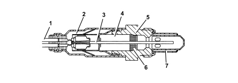
1. Connecting element
2. Protective sleeve
3. Planar sensor element
4. Ceramic support pipe
5. Sensor seat
6. Ceramic seal
7. Protective pipe
The Lambda sensor works on the principle of an oxygen concentration chamber with solid electrolyte.
The measurement chamber surfaces are coated with microporous layers of noble metals.
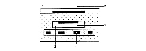
1. Exhaust gas
2. Reference air passage
3. Heater
ELECTRICAL SPECIFICATIONS:
- Heater power supply: 12 V
- Heater resistance: 0.5 - 1 kOhm.
CATALYTIC CONVERTER
The three-way catalytic converter makes it possible to reduce the levels of the three pollutant gases in exhaust gases at the same time:
- Unburnt hydrocarbons (HC);
- Carbon monoxide (CO);
- Nitrogen oxides (NOx).
Two types of chemical reaction take place inside the catalytic converter:
- Oxidation of CO and HC to carbon dioxide (CO2) and water (H2O)
- Reduction of NOx to nitrogen (N2).
The converter consists of a structure, a metal gauze support to dampen impacts and vibrations, and a stainless steel outer casing that is resistant to high temperatures and atmospheric agents.
The honeycomb structure is made from a ceramic material covered in an extermely thin layer of catalytically active substances, platinum or rhodium, which accelerated the chemical decomposition of the harmful substances contained in the exhaust gases which, when passing through the core cells at temperatures above 300 ° - 350°C, activate the catalyzers setting off the oxidation/reduction reactions.
A perforated steel cone improves the diffusion of the exhausts gases in the ceramic core cells to ensure the optimum efficiency and lifespan of the catalyzer.
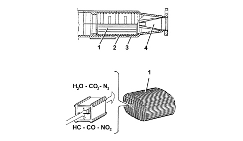
1. Ceramic structure
2. Metal support
3. Outer casing
4. Perforated steel cone
The noble metals in the catalytic converter suffer chemical attack if lead is present, partly due to the high temperature inside the converter. For this reason, the use of leaded fuel should be be avoided, otherwise the converter will be rapidly and irreversibly put out of service. Never use leaded fuel, not even for a short time or in an emergency.
DESCRIPTION OF COMPONENTS
CATALYTIC CONVERTER
Specifications
The catalytic converter is a post-treatment device for oxidizing the CO, HC and particulate, converting them into carbon dioxide (CO2) and water vapour (H20).
The catalytic converter consists of a ceramic, honeycomb structure (1) with cells impregnated with platinum (2) which catalyzes the oxidation reactions.
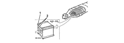
Operation
The exhaust gases passing through the cells heat the catalyzer, triggering the conversion of pollutants into inert compounds.
The oxidising chemical reaction of the CO, HC and particulate is effective at temperatures of between 200 and 350°C.
Actually, above 350°C the sulphur contained in the diesel fuel starts to oxidise, producing sulphur dioxide and sulphur trioxide.
DPF SYSTEM (Diesel Particulate Filter)
This is a mechanical filter that "traps" the carbon particles (particulate) and the engine oil ashes in the exhaust gases in diesel engines.
The action of the DPF makes it possible to keep carbon particle levels down by around 90% in line with Euro 4 and 5 regulations.
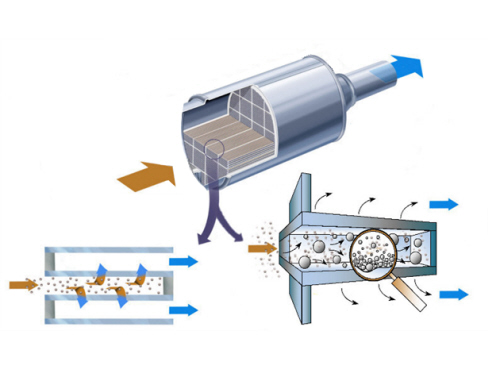
The operation of the DPF system is managed by the engine injection control unit by means of suitable strategies. In addition to the actual filter the DPF system comprises an exhaust gas temperature sensor and a differential pressure sensor.
The differential pressure sensor measures the pressure of the exhaust gases downstream of the filter, by means of a special pipe, signalling the gradual accumulation of particulate to the control unit. The particulate accumulation process and the relative increase in the pressure of the exhaust gases inside the filter depends on the engine load, the weight of the vehicle and the engine capacity and power. Therefore the particulate needs to be removed on a regular basis, regenerating the filter following a procedure that makes use of multiple injections to increase the temperature of the exhaust gases (about 600°C) and burn the particulate. The regeneration procedure is controlled by the injection control unit which acts: on the metering of the fuel (up to five injections in the same engine cycle per cylinder) and on the control of the air (E.G.R. and supercharging pressure).
The regeneration phase takes place over a few minutes and does not affect the continuity of the torque supplied by the engine in terms of normal operation.
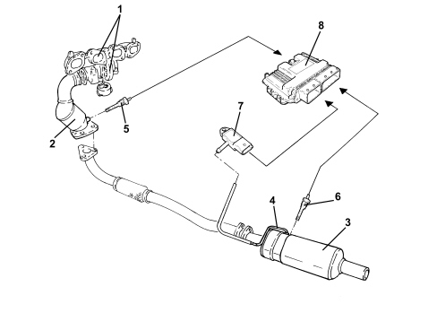
- 1 Turbocharger-exhaust manifold assembly
- 2 Catalytic converter
- 3 Filter
- 4 Exhaust gas pressure intake
- 5 Exhaust gas temperature sensor downstream of the catalyzer
- 6 Exhaust gas temperature sensor downstream of the filter
- 7 Relative pressure sensor
- 8 Injection control unit
Relative pressure sensor
The exhaust gas relative pressure sensor fitted on diesel versions with particle filters (DPF) is installed in the engine compartment and connected to the pressure intake upstream of the particle filter by means of a pipe resistant to high temperatures. It continuously provides information for the engine management control unit on the pressure value upstream of the filter (a value closely connected to the filling state). The pressure information, compared with atmospheric pressure, is communicated to the engine management control unit which, by means of a specific algorhithm, recalculates it subtracting the fall in pressure at the silencer thereby obtaining the difference in pressure at the sides of the filter. The purified signal is used, together with the estimate of the volumetric flow rate of the gases at the filter intake, to calculate the filter blockage status index. This index is constantly compared with a safety level (value for the blocked filter) which, if exceeded, activates the diagnosis and the switching on of the injection warning light. This diagnostic function guarantees that the safety level which is dangerous for the operation of the filter, the durability of the filter and the exceeding of normal operating temperatures is never exceeded.
The exhaust gas relative pressure sensor fitted on diesel versions with particle filters (DPF) is installed in the engine compartment and connected to the pressure intake upstream of the particle filter by means of a pipe resistant to high temperatures.
It continuously provides information for the engine management control unit on the pressure value upstream of the filter (a value closely connected to the filling state).
The pressure information, compared with atmospheric pressure, is communicated to the engine management control unit which, by means of a specific algorhithm, recalculates it subtracting the fall in pressure at the silencer thereby obtaining the difference in pressure at the sides of the filter.
The purified signal is used, together with the estimate of the volumetric flow rate of the gases at the filter intake, to calculate the filter blockage status index.
This index is constantly compared with a safety level (value for the blocked filter) which, if exceeded, activates the diagnosis and the switching on of the injection warning light.
This diagnostic function guarantees that the safety level which is dangerous for the operation of the filter, the durability of the filter and the exceeding of normal operating temperatures is never exceeded.
The operation of the sensor is based on the variation in the resistance value of a piezoceramic element which, by means of an electronic amplification circuit and signal compensation, translates the pressure value operating on the sensitive element into a voltage value (0-5V).
The relative pressure sensor measures the relative pressure (p4) before the particle filter and the ambient pressure (p amb).
The sensor calculates the difference in pressure betwen the two values measured: pe = p4 - pamb.
The pressure sensor piezoresistive element and the circuits adopted for the amplification of the signal and the compensation of the temperature are incorporated in a silicon chip.
The pressure p4 acts on the rear of the silicon diaphragm which is resistant to corrosive agents.
The reference pressure pamb operates ont he active side of the silicon diaphragm.
The maximum permitted values for the correct operation of the sensor are given below:
maximum supply voltage: 16V
maximum relative pressure (p4max): 500 KPa
maximum difference in pressure (pemax): 400 KPa
temperature interval: between -40 and +130°C
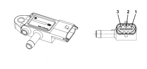
- 1 5V power supply
- 2 earth
- 3 signal
Transfer function
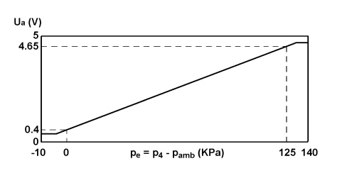
The sensor voltage output signal varies depending on the relative pressure in accordance with the law:
Ua = (c1*pe+c0)+Us
Where:
Ua = signal output voltage in V
Us = supply voltage in V
Pe = differential pressure in KPa
c0 = 0.08
c1 = 0.068 Kpa-1
Exhaust gas temperature sensors
Specifications
Pull-up power supply: 5 V +/- 0.1%
Pull-up resistance: 1000 Ohm +/- 0.1%
Rated resistance at 0ºC: 200 Ohm
Operating range: between -30°C and +120°C
Operation
The exhaust gas temperature sensors fitted on diesel versions with particle filters (DPF) are installed downstream of the precatalytic converter (front sensor) and downstream of the catalytic converter (rear sensor positioned immediately before the particle filter). They provide current and continuous information for the engine management control unit and have two distinct functions.
The front sensor carries out the precatalytic converter temperature protection function, whilst the rear one checks that the regeneration temperature of the filter is within the safety limits and at a value that guarantees the complete combustion of the particulate.
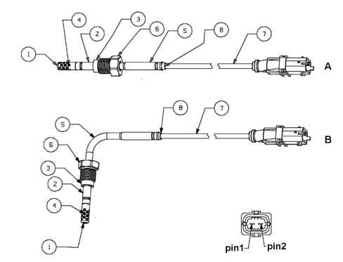
- A - sensor with straight casing
- B - sensor with casing bent at 90° angle
- 1 Terminal protection
- 2 Protective pipe
- 3 Flange
- 4 Thermal coupling
- 5 Rigid cable
- 6 Fixing ring nut
- 7 Flexible cable
- 8 Teflon pipe
The electrical opration of the sensors is always monitored/diagnosed whilst a diagnostic check on the consistency of the value measured compared with the other temperature sensors in the engine management system is only carried out during starting.
The two sensors are identical in operation and the only differences are linked to the depth of the immersion of the sensitive element in the pipe (prominence of the push rod), the differences in the geometry of the casing (sensor with straight casing or casing bent at a 90° angle) and to the length of the electrical bridge connected to the injection wiring.
The operation of the sensor is based on the variation of the value of a platinum resistance with thin film technology depending on the temperature (a variation with an almost linear law, curve A).
Curve B illustrates the variation in voltage sent directly to the engine management control unit which, by means of a conversion map, translates the voltage value into temperature
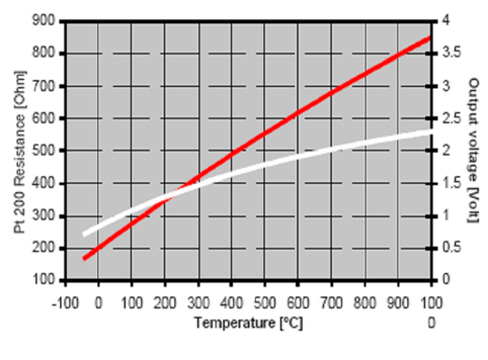
The table below contains the resistance values for the sensor with a straight casing depending on the exhaust gas temperature
| Temperature (°C) | Resistance (ohm) |
|---|---|
| -40 | 169,7 |
| -20 | 185,1 |
| 0 | 200,5 |
| 25 | 219,6 |
| 50 | 238,5 |
| 100 | 275,9 |
| 150 | 312,7 |
| 200 | 349,0 |
| 250 | 384,6 |
| 300 | 419,7 |
| 400 | 488,1 |
| 500 | 554,1 |
| 600 | 617,8 |
| 700 | 679,2 |
| 800 | 738,2 |
| 900 | 794,9 |
| 1000 | 849,2 |
The table below contains the resistance values for the sensor with a casing at a 90° angle depending on the exhaust gas temperature
| Temperature (°C) | Resistance (ohm) |
|---|---|
| -40 | 170,2 |
| -20 | 185,6 |
| 0 | 201,0 |
| 25 | 220,1 |
| 50 | 239,0 |
| 100 | 276,4 |
| 150 | 313,2 |
| 200 | 349,5 |
| 250 | 385,1 |
| 300 | 420,2 |
| 400 | 488,6 |
| 500 | 554,6 |
| 600 | 618,3 |
| 700 | 679,7 |
| 800 | 738,7 |
| 900 | 795,4 |
| 1000 | 849,7 |
Lambda sensor
The "planar" type UEGO linear sensor is fitted on the front section of the exhaust pipe (downstream of the turbocharger) and informs the engine management control unit of the progress of the combustion.
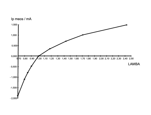
The sensor is an oxygen sensor containing two comparative cells that make it possible to measure Lambda values (ratio between the quantity of intake air and the theoretical quantity of air required for the complete combustion of the fuel injected) between a wide range from Lambda = 0.7 (rich mixture) to the value in air (Lambda = infinity lean mixture).
It is used to compare the reading of the air flow meter with the one mapped in the control unit and, if necessary, correct the fuel injection to be within the emission limits.
The sensor works by comparing the concentration of oxygen in the reference cell, housed inside the sensor, with the combustion gas flowing inside the comparison cell next to the reference cell. Depending on the resulting imbalance, the engine management control unit regulates a current signal (lp) that rebalances the oxygen content in the comparison cell through an electrochemical action. The value of lp is proportional to the Lambda value measured according to the graph illustrated below.
In order to activate the operation of the sensor quickly, the sensor contains a heater operated in duty cycle by the engine management control unit according to a calibrated strategy.
The two comparison cells and the heater are incorporated in the same flat ceramic element (layers of several ceramic elements) in order to keep the structure compact and guarantee high response and heating speeds for the element itself.
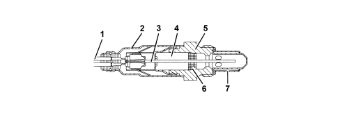
- 1 Connection cable
- 2 Protective sleeve
- 3 Planar sensor element
- 4 Ceramic mounting pipe
- 5 Sensor housing
- 6 Ceramic seal
- 7 Protective pipe
The Lambda sensor works on the principle of an oxygen concentration chamber with solid electrolyte.
The measurement chamber surfaces are coated with microporous layers of noble metals.
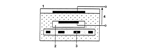
- 1 Exhaust gas
- 2 Reference air passage
- 3 Heater
- 4 Lambda sensor voltage
Specifications
Supply: 12V
Internal resistance: 0.5 - 1 kOhm
The Lambda sensor connector is illustrated in the diagram below.
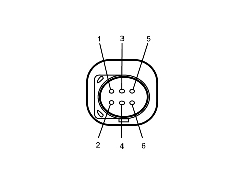
- 1 Pumping current (lp)
- 2 Virtual mass
- 3 Heater (-)
- 4 Heater (+)
- 5 Calibration current
- 6 Nerst voltage
LAMBDA SENSOR
Specifications
The "planar" type sensors are fitted upstream and downstream of the catalytic converter andinform the injection control unit of the progress of the combustion (stoichiometric ratio).
The Lambda sensors are used by the control unit for:
- checking the progress of the combustion (upstream Lambda sensor)
- carry out self-adjustment corrections (upstream Lambda sensor)
- checking the catalytic converter operating conditions (downstream sensor).
To produce an optimum mixture the quantity of air drawn in by the engine must be equal to the theoretical quantity required to burn all of the fuel injected.
In this case the Lambda factor ratio between the quantity of intake air and the theoretical quantity of air (required to burn all the fuel injected) is equal to 1.
Therefore:
- Lambda = 1 ideal mixture
- Lambda > 1 lean mixture
- Lambda < 1 rich mixture
a, Rich mixture (not enough air)
b, Lean mixture (too much air)
The Lambda sensors are in contact with exhaust gases and generate an electrical signal with voltage dependent on oxygen level in the gas.
This voltage alters abruptly when mixture composition deviates from Lambda = 1.
The injection control unit manages Lambda sensor heating in proportion to exhaust gas temperature.
This avoids thermal shocks to the ceramic case due to contact with condensed water present in exhaust gas when the engine is cold.
The measurement chamber and heater are built into a planar (laminated) ceramic element that offers the benefit of fast chamber heating. This allows closed loop (Lambda = 1) control within 10 seconds of engine start-up.
1. Connecting element
2. Protective sleeve
3. Planar sensor element
4. Ceramic support pipe
5. Sensor seat
6. Ceramic seal
7. Protective pipe
The Lambda sensor works on the principle of an oxygen concentration chamber with solid electrolyte.
The measurement chamber surfaces are coated with microporous layers of noble metals.
1. Exhaust gas
2. Reference air passage
3. Heater
HEATER ELECTRICAL PROPERTIES
Rated voltage: 12V
Maximum voltage: 14V
Rated power: 7W
Resistance: 9 Ohm at 20 °C
Maximum current: 2.1 A at 13V
ELECTRICAL CONNECTIONS

Pin 1, Signal
Pin 2, Earth signal
Pin 3, Heater control
Pin 4, Power supply 12V
CATALYTIC CONVERTER
At the same time, the three-way catalytic converter makes it possible to reduce the levels of the three pollutant gases present in exhaust gases:
- Unburnt hydrocarbons (HC);
- Carbon monoxide (CO);
- Nitrogen oxides (NOx).
Two types of chemical reaction take place inside the catalytic converter:
- Oxidation of CO and HC to carbon dioxide (CO2) and water (H2O)
- Reduction of NOx to nitrogen (N2).
The converter consists of a structure, a metal gauze support to dampen impacts and vibrations, and a stainless steel outer casing that is resistant to high temperatures and atmospheric agents.
The honeycomb structure is made from a ceramic material covered in an extermely thin layer of catalytically active substances, platinum or rhodium, which accelerated the chemical decomposition of the harmful substances contained in the exhaust gases which, when passing through the core cells at temperatures above 300 ° - 350°C, activate the catalyzers setting off the oxidation/reduction reactions.
A perforated steel cone improves the diffusion of the exhausts gases in the ceramic core cells to ensure the optimum efficiency and lifespan of the catalyzer.
1. Ceramic structure
2. Metal support
3. Outer casing
4. Perforated steel cone
The noble metals in the catalytic converter suffer chemical attack if lead is present, partly due to the high temperature inside the converter. For this reason, the use of leaded fuel should be be avoided, otherwise the converter will be rapidly and irreversibly put out of service. Never use leaded fuel, not even for a short time or in an emergency.
Parts & tools for this job For 2007 Fiat Bravo
- PARTExhaust gasketSearch: Fiat Bravo 2007 exhaust gasket
- TOOLPenetrating oilSearch: penetrating oil
- TOOLOBD2 scannerSearch: OBD2 scanner
Links open Amazon search results in a new tab. As an Amazon Associate I earn from qualifying purchases.