
Rotation speed restricter (page 2 of 2)
- Make
- Fiat
- Model
- Bravo /Brava (182) Factory Service Manual
- Year
- 1995–2001
- Section
- Fuel system (98 range, 1242 16v)
The management of the ignition basically consists of determining the desired ignition advance according to the engine operating conditions and its implementation through the operation of the power transistor located inside the control unit.
The "basic" advance value, calculated on the basis of the engine load and speed conditions, is then corrected according to the different engine operating conditions.
The primary winding for each coil receives the battery voltage via the relay and is connected to the power transistor incorporated in the engine control unit, whose transmitter is connected to earth, whilst base receives the operating voltage from the control unit.
According to the engine rotation speed and the ignition advance to be implemented, the engine control unit establishes the moment for the start of the conduction of the primary winding, in such a way as to reach the desired current intensity (saturation) in the primary winding immediately before this current is interrupted.
This moment obviously varies in terms of the angle in relation to TDC for the explosion stroke for each cylinder and the greater the advance, the greater the engine rotation speed because the time required to saturate the current in the coil primary winding is more or less constant: it is determined using suitable coefficient stored in the memory (dwell management).
The moement for the start of conduction is also corrected on the basis of the battery voltage.
The engine control unit therefore determines the moment the current in the primary coil is interrupted transforming the advance degrees into the time required by the engine to cover this angle: this time constitutes the advance in relation to TDC for the explosion stroke with which the current is interrupted at the base of the transistor.
The moment the current at the base of the power transistor is interrupted, the connection to earth for the primary coil is interrupted and consequently there is a high tension discharge at the secondary winding.
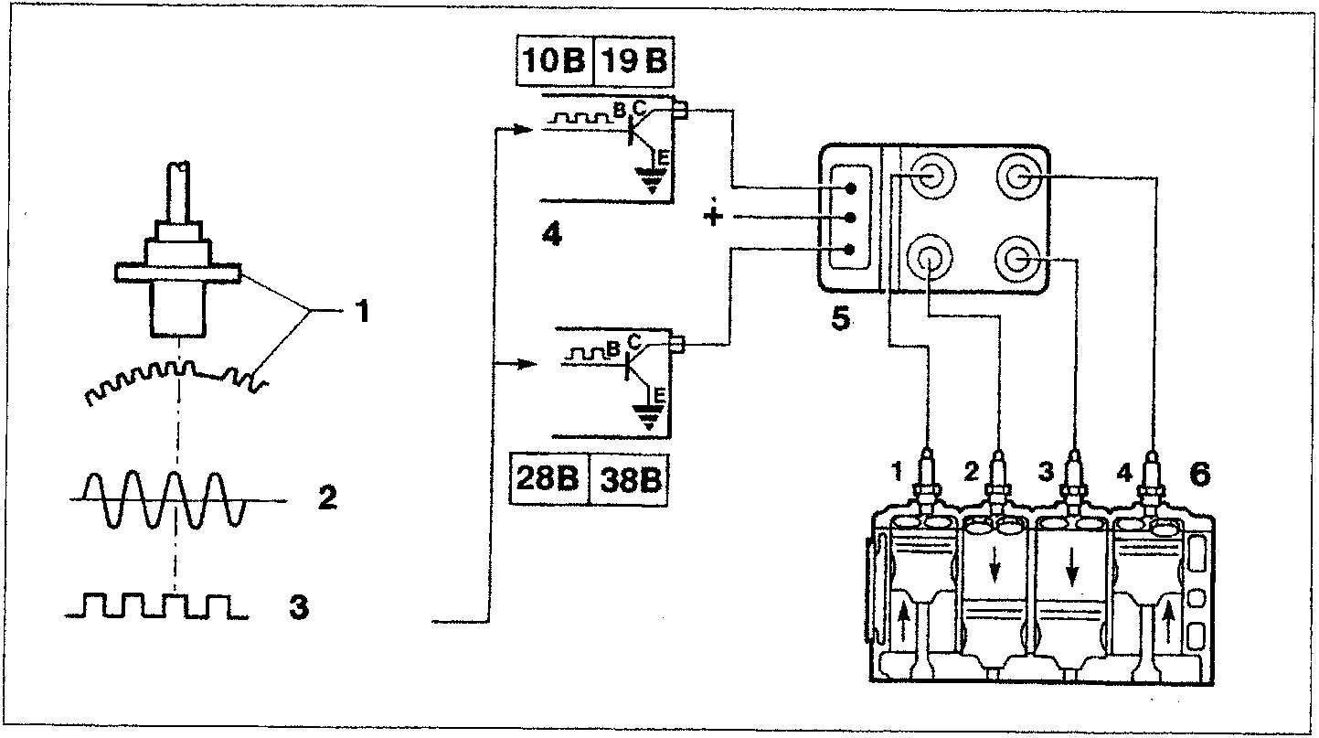
- Engine rpm and TDC sensor and flywheel
- Control unit input signal
- Signal converter in the control unit (square wave)
- Internal power module
- Coil
- Spark plugs
Parts & tools for this job For 1995 Fiat Bravo
- PARTFuel filterSearch: Fiat Bravo 1995 fuel filter
- TOOLFuel pressure test kitSearch: fuel pressure test kit
- TOOLFuel line disconnect toolSearch: fuel line disconnect tool
Links open Amazon search results in a new tab. As an Amazon Associate I earn from qualifying purchases.